Test 6aFigure 27: Test 7Figure 28: Test 6Figure 26:
Remove any one pump wire and re-make the connection
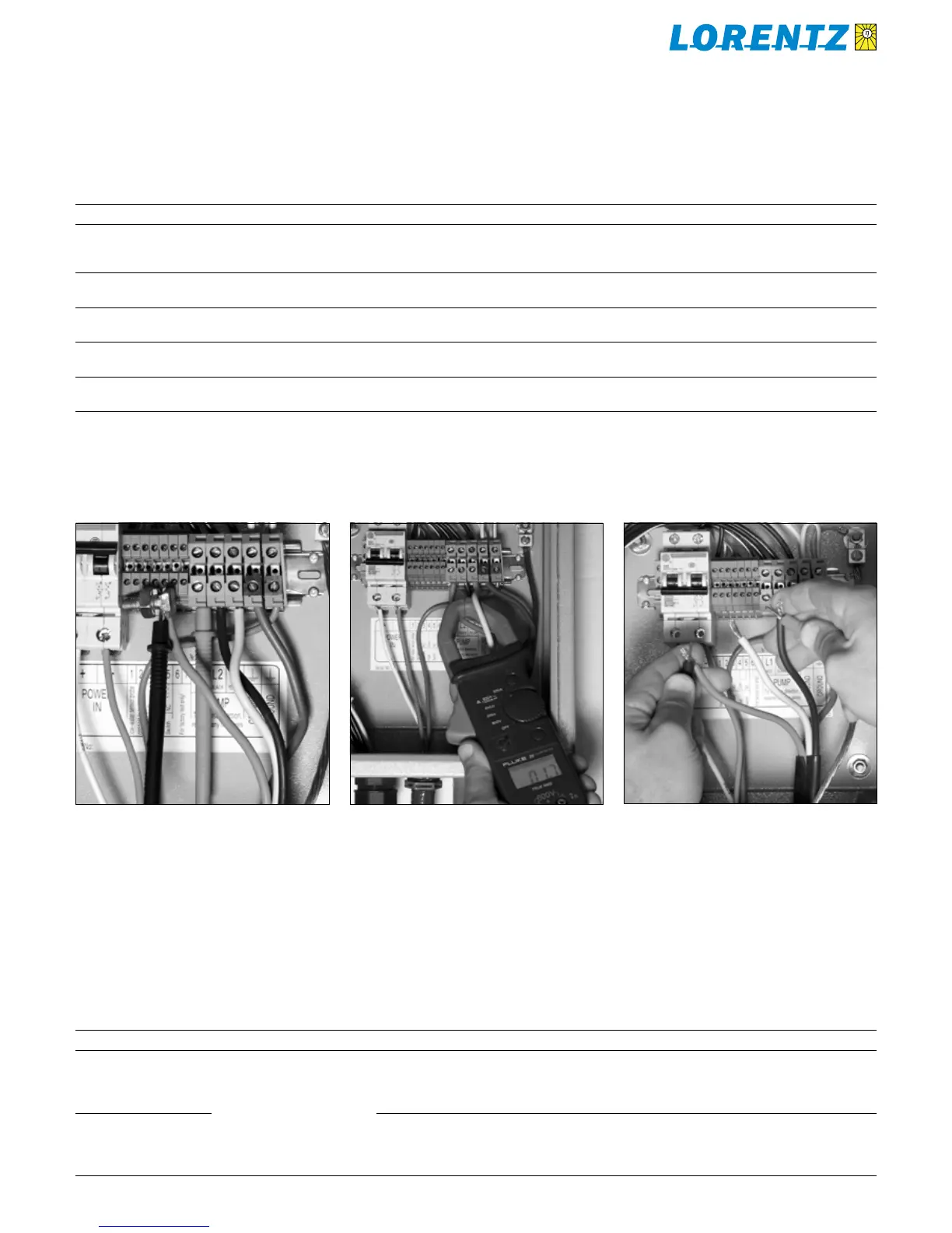
THROUGH your meter. Probe connections must be secure.
A clamping device is helpful (split bolt is shown as an
example).
Testing the pump circuit (AC and resistance)Table 8:
Test Test Description Notes Meter Setting + Probe Input Normal Result Interpretation
5 pumping speed
during pumping
count number of flashes
on PUMP ON LED
- - 1 to 5 flashes
varies with the sun intensity
number of flashes indicates motor
speed (RPM) and ensures that the
motor is spinning
6 motor AC current
draw
measure any of the three
motor wires
A AC 10A
or higher
1 – 9 A
see table in section 9.3
current is proportional to
the torque load on the motor
6A same, using clamp-
on ammeter
This type of meter is
easierst to use.
A AC - 1 – 9 A
see table in section 9.3
current is proportional to
the torque load on the motor
7 pump circuit
resistance
Power OFF, measure all:
L1 – L2, L1 – L3, L2 – L3*
Ω Ω 0.1 – 1.5 Ω
all three must be equal
normal and equal means that motor,
cable and splices are fine
8 pump circuit
resistance to ground
Measure from any pump wire to
ground
Ω Ω more than 100kΩ lower reading indicates
an insulation fault
Testing the pump circuit (AC and resistance)9.2
*) Resistance: Hold the probes tightly to the wire and
scratch them to ensure good contact. Hold them still until
the meter display shows the LOWEST reading that you can
get. Holding the probes with your fingers will not alter the
reading.
Analog (mechanical) meter requires zero-adjustment. For
this test, you can touch probes with your fingers.
Testing the low-water probe circuitTable 9:
Test Test Description Notes Meter Setting + Probe Input Normal Result Interpretation
9 POWER ON
voltage at terminals
1 and 2
chose one of
these two tests
V DC V ... a) 0 – 2 V
b) 5 V
if a) pump in water or bypassed
– pump on
if b) probe above water or circuit
broken – pump off
9 resistance between
probe wires, discon-
nect from controller
Ω Ω ... a) < 100 Ω
b) > 10 kΩ
if a) probe in water – OK
bypassed – pump on
if b) probe above water or circuit
broken – pump off
Testing the low-water probe circuit9.3
 Loading...


