Trouble Shooting8
Please read this section before calling for help.
If you call for help, please refer to the model and serial
numbers. See section 1, System Report
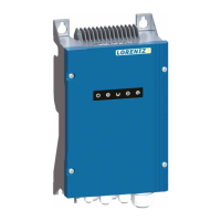
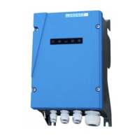
IF THE CONTROLLER MUST BE
REMOVED FOR REPAIR OR REPLACE-
MENT Remove the wires and flexible
conduit from the controller and
remove the CONTROLLER ONLY. LEAVE THE
JUNCTION BOX IN PLACE.
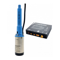
CAUTION DO NOT REMOVE THE
CHECK VALVE from the pump. If you
want to look for dirt stuck inside the
pump, it is preferable to unbolt the
pump body and pull it from the pump. IF YOU MUST
REMOVE THE CHECK VALVE, use a hardening
adhesive sealant on the screw threads when you
replace it. Epoxy glue is good. The threads are not
tapered. They will leak if a hardening sealant is not
used. Teflon tape will make a good seal, but it may
not prevent the joint from unscrewing.
If The Pump Does Not Run8.1
Most problems are caused by wrong connections (in a new
installation) or failed connections, especially where a wire
is not secure and falls out of a terminal. The System ON
light will indicate that system is switched on and connected
to the controller. It indicates that VOLTAGE is present but
(in a solar-direct system) there may not be sufficient power
to start the pump. It should attempt to start at intervals of
120 seconds.
Pump attempts to start every 120 seconds but does
not run The controller makes a slight noise as it tries to
start the pump. The pump will start to turn or just vibrate
a little.
There may be insufficient power reaching the 1.
controller. A solar-direct (non-battery) system should
start if there is enough sun to cast a slight shadow.
A battery system should start if the supply voltage is
greater than 22 V (24 V system) or 44 V (48 V system).
If the pump was recently connected (or reconnected) 2.
to the controller, it may be running in reverse direc-
tion due to wiring error. See section 5.8, Wiring Order
for Correct Rotation
If the motor shaft only vibrates and will not turn, it 3.
may be getting power on only two of the three motor
wires. This will happen if there is a broken connection
or if you accidentally exchanged one of the power
wires with the ground wire. See section 9.3, Electrical
Testing
The pump or pipe may be packed with mud, clay, 4.
sand or debris.
Was the pump stored in water for more than three 5.
months? This might cause the pump to seize. Pumps
will not be damaged, but might have to be pulled
to free them again. Let stored pumps run every 2 – 3
months in order to avoid seizure.
Helical rotor models: The rubber stator may be 6.
expanded from heat, due to sun exposure or pump-
ing water that is warmer than 72°F (22°C). This may
stop the pump temporarily, but will not cause dam-
age. See section 12, Temperature Specifications
Helical rotor models: The pump may have run dry. 7.
Remove the pump stator (outer body) from the mo-
tor, to reveal the rotor. If there is some rubber stuck
to the rotor, the pump end must be replaced.
Helical rotor models: The check valve on the pump 8.
may be faulty or stuck, allowing downward leakage
when the pump is off. This can prevent the pump
from starting.
Is the pump installed in a negative suction head 9.
application? This is an abnormal situation and will
pull the rotor out of the pump stator causing possible
damage inside the motor as this is an abnormal
working direction for all pumps. Negative suction
head means that you do not need a pump at all since
the delivery point is below the water source level in
the source (wells, ponds etc.) See also section 6.1,
Warnings for Handling Helical Rotor Pumps, WARN-
ING about siphon applications
PUMP OVERLOAD (PUMP ON light shows red
instead of green) The system has shut off due to an
overload. This can happen if the motor or pump is blocked
or very difficult to turn and is drawing excessive current
(hard to turn). Overload detection requires at least 250 W
output of the solar array. This can be caused by a high con-
centration of solids in the pump, high water temperature,
excessive pressure due to high lift or a restriction in the
pipe, or a combination of these factors. The controller will
make 3 start attempts before shutting down the system.
The System ON LED will be OFF and the red OVERLOAD
LED ON. The system will not reset until the ON / OFF switch
is turned OFF and ON again. See Troubleshooting, section
9.3, Electrical Testing: Higher Current
Many problems can be located by simple inspection. No
electrical experience is required.
 Loading...


