Testing the Solar Array (DC)Table 7:
Test Test Description Notes Meter Setting + Probe Input Normal Result Interpretation
1 PV array
open-circuit voltage
POWER IN switch must be OFF
Check +/- polarity
V DC V ... 75-85 V
lowest in hot weather
half or twice the normal indicates that
the array is wired wrong
2 PV array
short-circuit voltage
POWER IN switch must be OFF
WARNING Do not connect
short-circuit for more than 1/2
minute. A spark is normal.
A DC 10 A
or higher
maximum equal to
PV array Watts divided by 65
varies with sun intensity
indicates that the solar array is produc-
ing the expected amount of current,
independent of the pump system
2A same, but using a
clamp-on ammeter
WARNING Do not connect
short-circuit for more than 1/2
minute. A spark is normal.
A DC
check zero-adjust
no probes maximum equal to
PV array Watts divided by 65
varies with sun intensity
indicates that the solar array is produc-
ing the expected amount of current,
independent of the pump system
3 DC input voltage
during pumping
- V DC V ... around 60 V
lowest in hot weather
indicates proper controller input
function
4* DC input current
during pumping
- A DC 10 A
or higher
maximum equal to
PV array Watts divided by 70
varies with sun intensity and
water lift
indicates whether the PV array is
delivering the expected current to the
pump
4A* same, but using a
clamp-on ammeter
This type of meter is easiest to use;
no need to break circuit.
A DC no probes maximum equal to
PV array Watts divided by 70
varies with sun intensity and
water lift
indicates whether the PV array is
delivering the expected current to the
pump
Testing the Solar Array (DC)9.1
This test refers to a 48 V solar array with a PS600
pump set. Your system voltage may vary.
*) Test 4 and 4A: The current is determined by both the ar-
ray AND the load (current draw of the pump system). If the
pump is not under full load (like in a bucket), the current
may be as little as 1 amp.
BATTERY SYSTEMS Perform tests # 1, 3 and 4 (4 A),
as above Normal result for #1 should equal the battery
voltage, typically 44-58 V Normal result for #3 is slightly
lower, not more than 2 V lower.
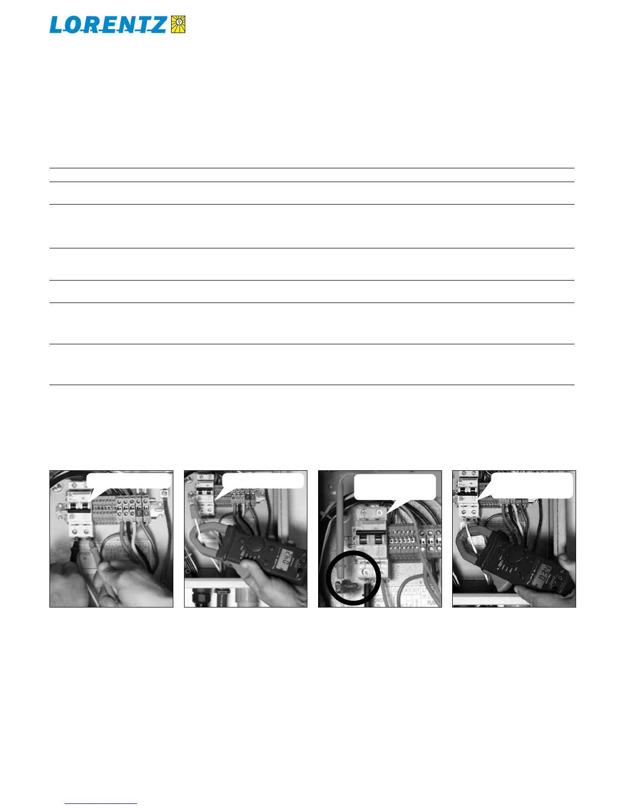
Test 1+2Figure 22: Test 4aFigure 23: Test 2aFigure 24: Test 4Figure 25:
PV disconnect switch OFF PV disconnect switch ON
PV disconnect switch ON
and pump running
PV disconnect switch ON
and pump running
Test 3: same as 1 + 2,
but disconnect switch ON
Remove one array wire and re-make the
connection THROUGH your meter. Probe
connections must be secure. A clamping
device is helpful (split bolt is shown as an
example).
DC clamp-on meter must be zero-set first