Controller Installation 3332 Controller Installation
EN EN
Relay
11 connect to NC
Potential-free signal output to control
third party devices; must be congured
with LORENTZ Assistant; either NC or NO
operation can be used
Maximum switching capability remote
switch: 250 V AC / 30 V DC, 2 A
12 connect to COM
13 connect to NO
Water
detection
sensor
14 optional: connect positive (+)
Connect water detection sensor for
surface pumps – for submersible pumps
a jumper wire is needed between 15+16.
If necessary, use 24 V DC supply from
terminal 14. The connected sensor must
not draw a higher current than 20 mA, if
the optional power terminal is used.
15 connect to Signal
16 connect to GND
SunSensor
module
17 connect positive (+)
Connect the SunSensor to terminal 17+18
and observe polarity. The SunSensor is
included with the PSk3 controller and
needed to protect the pump.
18 connect negative (–)
AC In
L1
connect to L1 phase of the AC
grid
Power supply from an AC source, e.g. a
generator or a grid connection
L2
connect to L2 phase of the AC
grid
L3
connect to L3 phase of the AC
grid
PE
connect to protective ground
wire (PE)
Solar IN
+
connect positive wire of PV
generator
Power supply from the PV generator
–
connect negative wire of PV
generator
Motor OUT
U connect to phase 1 of motor
Observe correct rotational direction of
pump
V connect to phase 2 of motor
W connect to phase 3 of motor
PE
connect to protective motor
ground wire (PE)
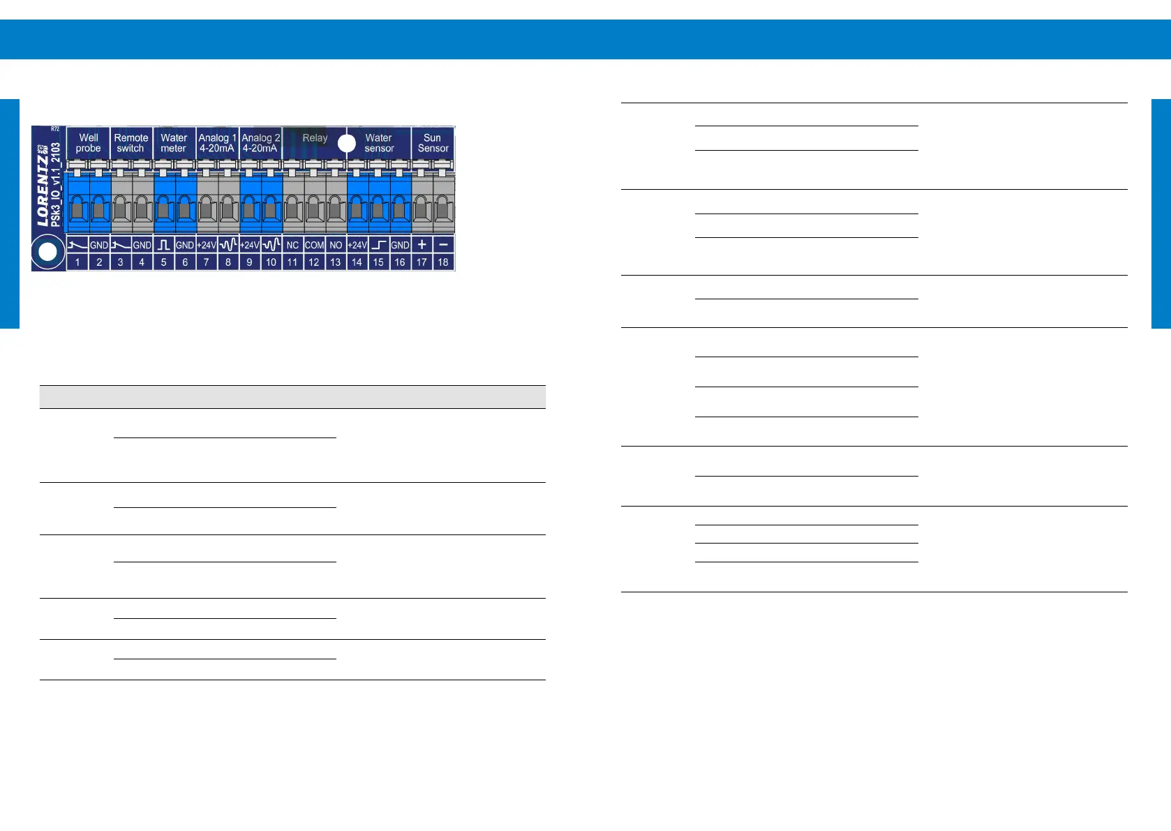
Figure 10: PSk3 sensor terminals
Table 5: Sensor terminal explanation
Socket Terminal Connection Function
Well probe
1 connect to NC
Connect a well probe or oat switch
to terminal 1+2 to protect the pump
system from running dry. Every pump
system must be equipped with a dry run
protection. Connect a jumper between 1+2
if not used.
2 connect to GND
Remote
switch
3 connect to NC
Connect a tank switch, pressure switch
or any other suitable remote switch to
terminal 3+4.Connect a jumper between
3+4 if not used.
4 connect to GND
Water meter
5 connect to Signal
Connect a device that provides a
potential-free impulse signal, e.g. a reed
contact. Water amount per impulse must
be congured with LORENTZ Assistant.
Allowed pulse rate ≤ 200 Hz.
6 connect to GND
Analog input
1 (4-20mA)
7 connect positive (+)
4 –20 mA signal sensor supply voltage
+24 V load impedance 100 Ω; observe
correct polarity
8 connect negative (–)
Analog input
2 (4-20mA)
9 connect positive (+)
4 –20 mA signal sensor supply voltage
+24 V load impedance 100 Ω; observe
correct polarity
10 connect negative (–)
COM = common; GND = ground; NC = normally closed; NO = normally open; PE = protective
earthing