Controller Installation 3534 Controller Installation
EN EN7.4.1. 3 PV Array Wiring
l
WARNING – When the photovoltaic
array is exposed to light, it supplies a DC
voltage to the PSk3 Controller.
WARNING – Do not ground solar!
Grounding solar when also using AC
power supply destroys the controller!
Failure to do so will result in signicant
damage to the controller.
It is the installers' duty to correctly size and
install the solar array, which includes all required
components like solar generator, cables, fuses,
combiner, disconnection devices and surge
protectors. Installation shall be made depending on
local installation requirements and conditions.
Only IEC 61730 compliant solar modules shall be
used with a system voltage rating of at least 1000 V
DC.
The pump system must be equipped with a proper
sized DC disconnect switch for safe installation and
maintenance of the controller. The switch must
be installed between the solar generator and the
controller. It must meet the following requirements:
minimum 850V DC
continuous current rating according to maximum
current of pump controller or higher
capable of carrying and switching the max. short
circuit current of the solar array
the switch must be rated for DC current, NOT AC
A PV disconnect switch that matches all these
requirements can be purchased from LORENTZ.
a
NOTE – The use of a properly sized
disconnect switch is an important
safety measure and mandatory for a
professional installation of a solar pump
system.
The diagram „Figure 12: Example conguration of
dierent components“ on page 37 provides an
example conguration. The exact requirements will
depend on the module conguration as dened in
COMPASS for the system being installed.
Electrical conduit
Electrical conduit is recommended. We recommend
the use of an electrical conduit (pipe) to protect
outdoor wiring from the weather, from human
activities and from damage caused by animals. If
you do not use a conduit, use a strong, high-quality
outdoor cable. Where cables enter the junction box,
install sealed strain relief cable glands.
7.4.1.4 Motor Wiring
7.4.1.4.1. Connecting the motor cable
The surface pump motor has a wiring box that
contains the connection terminals for the three
motor phases.
The pump motor provides bolt terminals to connect
the motor cable. For a professional and reliable
connection it is required to use cable lugs for
connecting the motor cable to the bolt terminals.
The motor phases are labeled with "U", "V", "W".
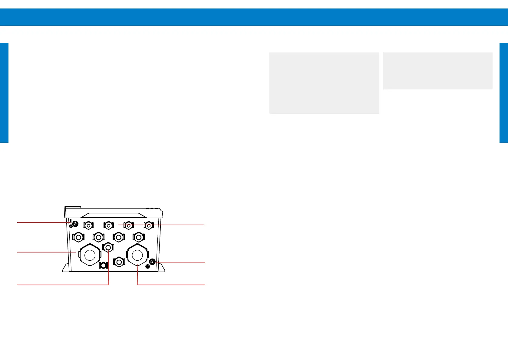
7.4.1. 2 Cable entries
There are cable glands of dierent diameters in the
bottom of the controller.
Power cables and accessories which use the cable
glands must be tightened properly in the glands for
strain relief and sealing.
If a power cable cannot be tightened because its
diameter is too small for the cable gland, a suitable
cable gland reducer has to be used to t the hole
of the cable gland to the cable diameter. Two sizes
of cable gland reducers are included with the PSk3
controller.
Figure 11: PSk3 controller front view
Sensor cable
glands
Outside grounding
bolt
Motor Out cable gland
On / o switch
AC input cable gland
Solar input cable
gland