S100 PROFInet Option Manual
The status transition explained in <10. PROFIdrive Operation Diagram> can be
performed by setting the four control word bits, from bit 0 to bit 3. For example, setting
the four bits to 1 (XXXX XXXX XXXX 1111) changes the status to “Operation.”
“X” in the bit setting example indicates that the relevant bit can be set to either 0 or 1
without affecting the control word bit settings.
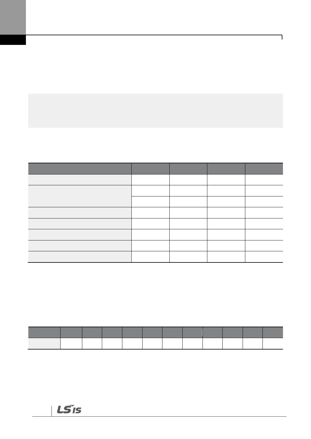
The following table lists the status transition controlled by the control word bits (Bits 0
to 3).
Internally, the control uses the inverter’s operation command at communication
address 0x0382, and the Control word (STW1) for basic motor operation uses
address 0x47F (bits 0, 1, 2, 3, 4, 5, 6, 10). When a PLC sets the bits at 0x47F, motor
operation is possible simply by providing a frequency reference.
Example) Bit Settings for Motor Operation
Note)
’-‘ indicates that the bit can be set to either 0 or 1 without affecting the motor operation.

 Loading...


