Appendix 3 Motor Wiring Example
App.3 - 3
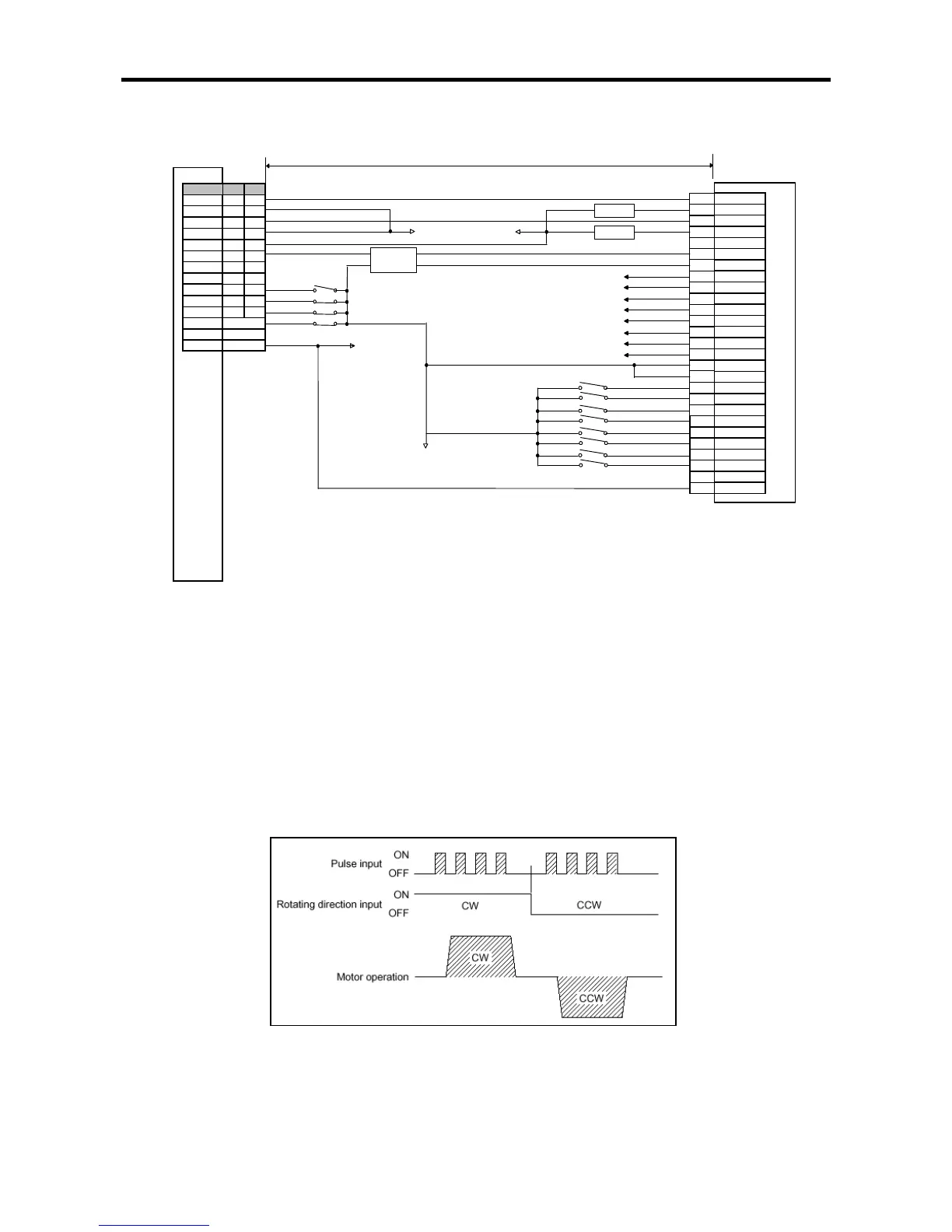
(2) Connection to a servo motor driver (FDA-5000 AC Servo Driver)
(Note1) The rating of XGB is 24VDC. If it is line driver output, contact is not connect
ed. In the case, use a convert from line
driver output to open collector output or use home return only by DOG signal/origin sensor of origin signal.
(Note2) Although origin, DOC, upper/lower limit signals are with fixed contact, it may be used for general
used. Emergency stop is available by the command (EMG).
(Note3) If using DC24V, make sure to connect resistor suitable for a driver (1.5K,1/2W) in series.
(Note4) Since the positioning pulse of XGB forward/reverse-rotates by the rota
tion direction as in the below figure, make
sure to change the input mode of a servo motor driver into 1 phase input mode prior to use.
PFIN
PPFIN
PRIN
1.5K,1/2W
1.5K,1/2W
Pulse
P20 P21
Signal Ch0 Ch1
Direction P22 P23
High limit
Low limit
Emg. stop