Do you have a question about the Lust CM-CAN1 and is the answer not in the manual?
Safety instructions and precautions for handling electrical drives and during installation.
Specifies suitability of CAN interface and processor performance for the system.
Explains user level in CAN bus interface and parameter documentation.
Lists related manuals and standards for drive unit and CAN bus.
Details CAN network multimaster capability, identifier rules, and access rights.
Explains how bus access rights are assigned based on identifier priorities.
Specifies identifier format (11-bit) and notes Extended format is not supported.
Details control and status message timing, including exceptions.
Lists CAN bus baud rates and maximum line lengths.
Describes CAN protocol integration and device addressing for LUST drives.
Explains device states, state machines, and their determination.
Outlines two control modes: EasyDrive and DRIVECOM state machine.
Details two methods for setting the device address: parameter or connector coding.
Provides instructions for mounting the CM-CAN1 module on different drive unit sizes.
Instructions for mounting the module on BG1-5 drive units.
Instructions for mounting the module on BG6-8 drive units.
Covers connecting the module to the field bus and wiring supply voltage.
Explains the hardware-based controller enable and its configuration.
Describes the function of the module's LEDs for status indication.
Step-by-step guide for the initial commissioning process of the drive unit.
Lists common reasons for drive units not responding to telegrams.
Troubleshooting guide for initialization errors and potential hardware faults.
Describes how to test CAN communication after changed settings.
Covers backing up and restoring device settings and factory defaults.
Details methods for backing up configuration data via KEYPAD or DRIVEMANAGER.
Explains how to reset the drive unit to its factory default settings.
Explains how parameter data is transmitted and interpreted in binary format.
Lists and describes the supported parameter data formats (e.g., USIGN8, INT32).
Shows how different data types are arranged in the data field (bytes).
Describes using preset solutions for bus operation and parameters changed automatically.
Overview and detailed description of parameters for CDA3000 bus operation.
Details parameters for CAN configuration, device address, and baud rate.
Explains how control location and reference source are selected via parameters.
Describes the process of backing up the device setup to Flash memory.
Explains how parameter numbers are represented as hexadecimal numbers.
Details acknowledgment of data transfers and mode-related access restrictions.
Describes how to access drive unit parameters via the parameter channel.
Explains the telegram sequence for reading string parameters.
Explains the telegram sequence for writing string parameters.
Covers the process and handshake for uploading complete parameter data sets.
Details the hardware enable requirement for CAN bus control.
Describes supported CAN system states: System logon, System Stop, System Start.
Explains device states, state machines, and their determination by commands and process.
Outlines two control modes: EasyDrive and DRIVECOM state machine.
Details control and status words for specific functions in EasyDrive mode.
Explains the DRIVECOM state machine and its reference input settings.
Defines base CAN identifiers for data transfer and station addressing.
Describes how stations operate with identifiers calculated by formula.
Explains broadcast transmissions received by all devices without reply.
Details the system logon process after power-on.
Describes the function of System Start and System Stop commands.
Explains how control functions are adapted and selected for applications.
Details how status and actual values are transmitted in START and STOP states.
Explains how error responses are indicated and programmed in four stages.
Lists error messages, their numbers, locations, and associated CAN bus errors.
Details bit-coded warning messages transmitted on the CAN bus.
Describes the function of the module's LEDs for system diagnosis.
Explains methods for acknowledging error messages, like using ENPO or parameter ERES.
Provides requirements and minimum parameter settings for activating a CDA3000.
Example of system logon and start sequence in EasyDrive control mode.
Example of system logon and control sequences for DRIVECOM state machine.
Example of enquiring and setting parameters for continuous actual value display.
CAN bus user group defining protocols for automation.
CAN Application Layer protocol describing variable transfer.
Based on CAL, expands definition for function and unit assignment.
| Brand | Lust |
|---|---|
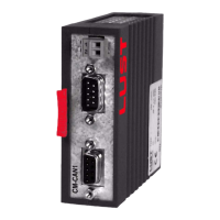
| Model | CM-CAN1 |
| Category | Control Unit |
| Language | English |