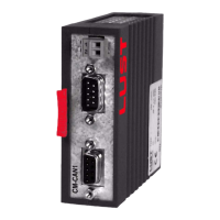
User Manual CM-CAN1
4-7
4 Setting the device parameters
DE
EN
1
2
3
4
5
6
7
A
4.3.1 General bus
settings
492-CACNF - CAN configuration
The parameter can be used to select the mode of activation via CAN.
With the DRIVECOM state machine the resolution of the reference input
and of the actual value can additionally be varied.
571-CLADR - CAN address
As described in section 2.1, the device address can be assigned in two
ways. The decisive factor is the setting of parameter 571-CLADR. If the
parameter is set to the value 0, the device address is ascertained after
system start from the connector configuration.
If the parameter is set to values between 1 and 99, the connector configu-
ration is ignored and the inverter starts after the reset with the device
address set in CLADR (save the setting prior to the reset with parameter
150-SAVE).
Subject area Value range Factory set. Unit Data type Memory type
_57OP 0 ... 4 4 – USIGN8 FLASH
CACNF Reference Actual Activation
0 No reference adopted No actual value transfer No activation
1
16-bit reference frequency
(Q0)
16-bit actual frequency (Q0)
DRIVECOM state
machine
2
32-bit reference frequency
(Q16)
32-bit actual frequency (Q16)
DRIVECOM state
machine
3
32-bit reference frequency
(Q16)
16-bit actual frequency (Q0)
16-bit actual torque (Q0)
*
DRIVECOM state
machine
4
32-bit reference frequency
(Q16)
32-bit actual frequency (Q16)
EasyDrive control
mode (CDA3000-
specific), factory
setting
* - Only in loop controlled operation
Table 4.6 CAN configuration
Subject area Value range Factory set. Unit Data type Memory type
_57OP 0 ... 99 0 – USIGN8 FLASH