User Manual CM-CAN1
6-7
6 Fault rectification
DE
EN
1
2
3
4
5
6
7
A
6.4 LED status
display on the
module
6.5 Acknowledg-
ment of error
messages
• By means of a rising signal edge at input ENPO
• Rising edge at a programmable digital input with function selector set
to ERES (e.g.: 231-FIS03 = (8) ERES)
• Writing of value 1 to parameter 74-ERES via control unit or bus
system. The entry is automatically deleted again.
• By way of the error reset bit in the control word
• Transition from SYSTEM START to SYSTEM STOP
After an error reset the state machine of the device (EasyDrive or
DRIVECOM) assumes the same state as after power-on. That is to say,
the control must be restarted.
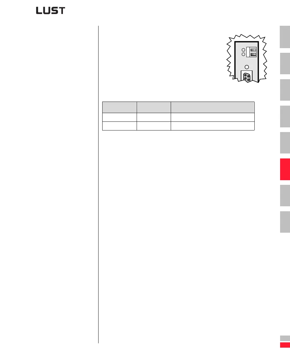
For initial system diagnosis, the module has two
LEDs (H4 and H5).
LED H5 indicates a correct voltage supply.
Red LED (H4) Green LED (H5) Bus state
Off Off 24V supply to module missing
Off On Voltage supply OK