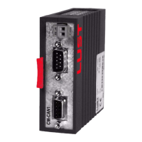
User Manual CM-CAN1
4-5
4 Setting the device parameters
DE
EN
1
2
3
4
5
6
7
A
4.2 Configuration of
the drive unit by
way of preset
application data
sets
For detailed information on preset solutions refer to section 4 of the Appli-
cation Manual.
Parameter 152-ASTER can be used to select from three preset solutions
for operation in field bus systems. These solutions differ only
in the func-
tion of digital inputs on the device. The control location and reference
source are assigned to the field bus system.
The following parameters are changed automatically in the device with
the setting e.g. 152-ASTER = BUS_1:
After the automatic configuration the baud rate and device address also
need to be set.
Note: The settings must be backed-up in the device before the
reset.
These changes only take effect after a mains reset.
Parameter
Factory setting
(FS)
Changed value Function
151-ASTPR DRV_1 BUS_1 Original application data set
152-ASTER DRV_1 BUS_1 Current application data set
180-FISA0 OFF OPTN2 Function selector analog standard input ISA00
181-FISA1 OFF OPTN2 Function selector analog standard input ISA01
210-FIS00 STR OPTN2 Function selector digital standard input ISD00
211-FIS01 STL OPTN2 Function selector digital standard input ISD01
212-FIS02 SADD1 OPTN2 Function selector digital standard input ISD02
213-FIS03 OFF OPTN2 Function selector digital standard input ISD03
240-FOS00 BRK1 OPTN2 Function selector digital standard output OSD00
241-FOS01 REF OPTN2 Function selector digital standard output OSD01
242-FOS02 S_RDY OPTN2 Function selector digital standard output OSD02
260-CLSEL * TERM OPTN2 Control location selector
280-RSSL1 * FMAX FOPT2 Reference selector 1
289-SADD1 * 10 0 Reference selector 2
* - These parameters must be changed as a minimum in order to enable control via the bus system.
Table 4.4 Presetting based on the example of BUS_1