2-6
User Manual CM-CAN1
2 Mounting and connection
2.3.1 Controller
enable (ENPO)
The drive units have an additional hardware-based controller enable from
the power stage (ENPO) via control terminal X2/8. This input must also
be configured for operation over the field bus.
This control signal is high-active. When this control signal is removed the
motor runs down uncontrolled (refer also to the description in the Opera-
tion Manual).
Figure 2.5 Configuration of controller enable ENPO on the CDA3000
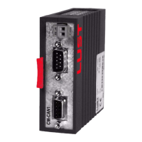
2.3.2 LED status
display
X2 Des. Function
9 ISD00 Digital input 1
8 ENPO Power stage hardware enable
7 UV
Auxiliary voltage 24 V
6 UV
For initial system diagnosis during commission-
ing, the communication module has two LEDs
(H4 and H5).
LED H5 indicates a correct voltage supply.
Red LED (H4) Green LED (H5) Bus state
Off Off 24V supply to module missing
Off On Voltage supply OK
Table 3.3 LED status display
ENPO