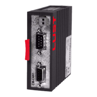
User Manual CM-CAN1
2-5
2 Mounting and connection
DE
EN
1
2
3
4
5
6
7
A
2.3 Electrical
installation
Figure 2.4 System connection. (1) Bus termination plug
Step Action Comment
1
Connect the module to the field bus. Use
a cable conforming to the specification.
Use a bus termination plug
(120 Ω) on the last module -
see Figure 2.4
2
Wire the controller enable on the
CDA3000.
see section 2.3.1
3
Wire up the supply voltage for the mod-
ule.
19 ...29 VDC see Table 3.2
4
Switch on the drive unit.
Electrical installation is finished; for the further procedure see section 3
“Commissioning and configuration”.
Characteristics CM-CAN1
Voltage supply 19 ... 29 V, supply optionally via X10, X11 or X12
Voltage ripple max. 3 Vss
Current consumption max. 80 mA per station
Cable type 9-wire, surge impedance 120
Ω
Table 3.2 Specification, CAN bus connection
L-
L1
L+
N
24 VDC
CAN-Bus
12
12
Slave 2
M
3~
Slave 1
M
3~
11 12 13 14
15 16 17 18 19
20
12
34567
89
10
11 12 13 14
15 16 17 18 19
20
1234
56789
10
SPS/PLC
12
Slave n
M
3~
(1)
1
120 E
2
7

 Loading...