User Manual CM-CAN1
5-7
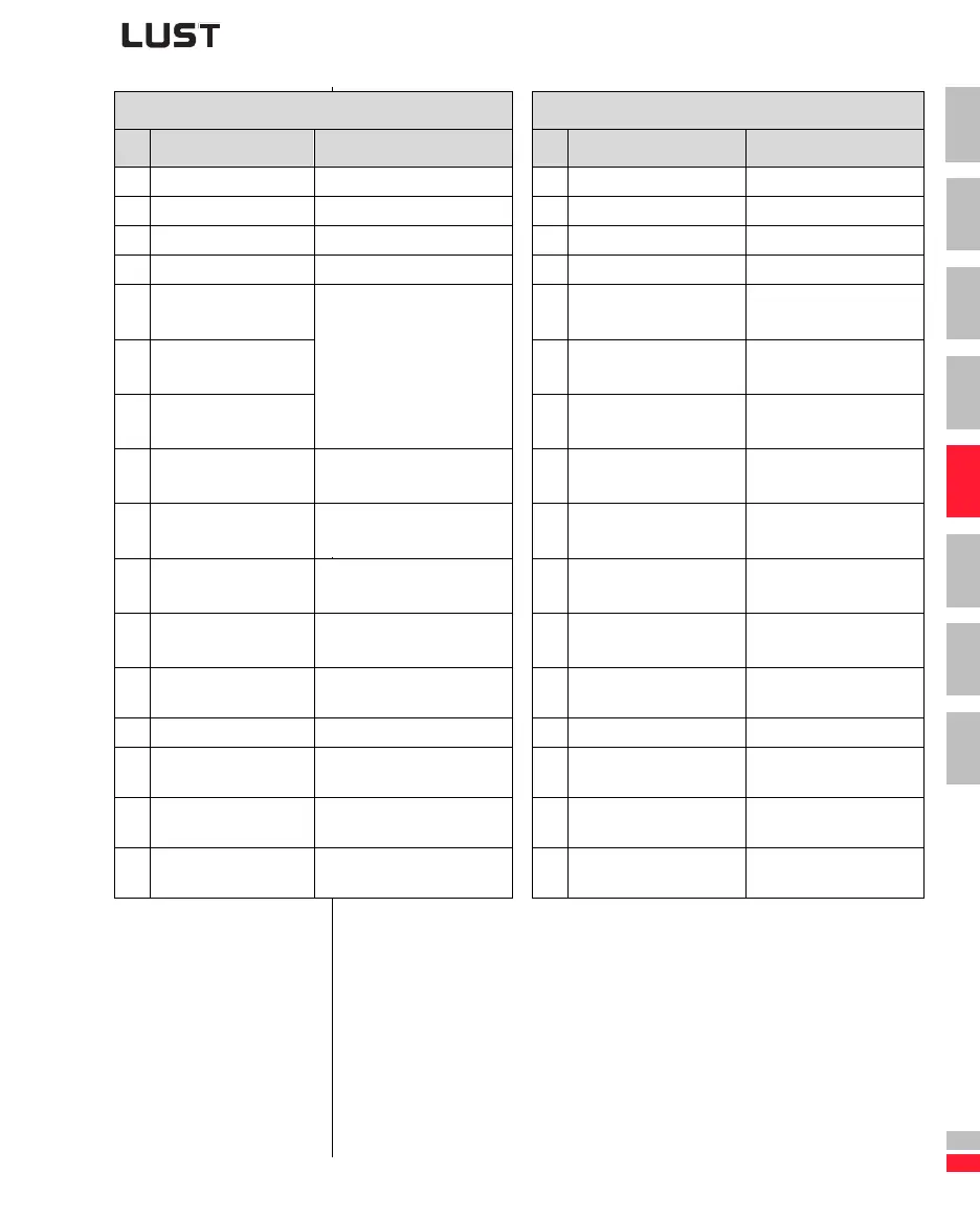
5 Control and reference input
DE
EN
1
2
3
4
5
6
7
A
* - Only if 280-RSSL1=(7) TBSEL
** - Only if 651-CDSSL=(6) OPTN2
*** - Only if 166-UDSSL=(3) OPTN2
Control word Status word
Bit Function Signal Bit Function Signal
0 Activate 0 Ready for start
1 Disable power 1 On
2 Emergency stop 1 = Emergency stop 2 Enable operation
3 Enable operation 3 Fault
4
FFTB0, select table ref-
erence (significance 2
0
) *
4
Power disabled 1 = Voltage disabled,
function not implemented
5
FFTB1, select table ref-
erence (significance 2
1
) *
Binary selection of a table
reference
1)
5
Emergency stop
6
FFTB2, select table ref-
erence (significance 2
2
) *
6
Switch-on inhibit
7
Reset fault 0->1 = Reset latest device
error
4)
7
Warning 1 = Warning delivered
8
CUSEL, data selection ** 0 = Characteristic data set 1,
1 = Characteristic data set 2
2)
8
CAN status 0 = System Stop
1 = System Start
9
UM0, select user mode
(significance 2
0
) ***
Binary selection of active user
mode
3)
9
Remote 1 = Parameter setting
possible
10
UM1, select user mode
(significance 2
1
) ***
10
Reference reached 1 = Reference reached
11
Vacant Vacant
11
Limit value 1 = Fmin Fmax limitation
active
12 Vacant Vacant 12 Status of input ISD03 Status of input ISD03
13
Reference status OSD02
if 242-FOS02=OPTN2
1 = Output OSD02 = high
13
Status of input ISD02 Status of input ISD02
14
Reference status OSD01
if 241-FOS01=OPTN2
1 = Output OSD01 = high
14
Status of input ISD01 Status of input ISD01
15
Reference status OSD00
if 240-FOS00=OPTN2
1 = Output OSD00 = high
15
Status of input ISD00 Status of input ISD00
Table 5.3 DRIVECOM control word and status word
 Loading...