LX7000 Mar.2002
Page 41
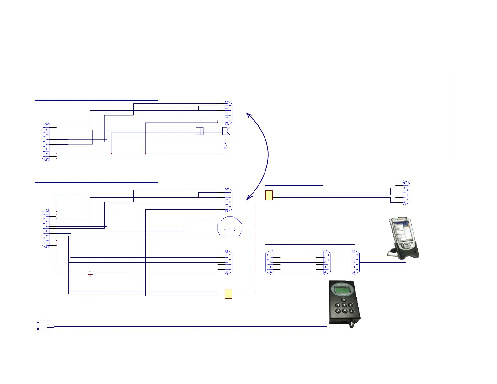
5.1 Wiring
5.1.1 Wiring (standard version)
1
6
7
4
9
5
SUBD15 Connector / female
LX7000 A NALOG UNIT
white
red
shield
black
yellow
GND
+12V
B
A
RS485 - IN
SPEAKER
SUBD 9 / male
GND
+12V DC IN
SC
1
9
2
10
3
11
4
12
5
13
6
14
7
15
8
TXD
RXD
B
A
Chinch
SC switch
Speak er
30 cm
30cm
0.5m
AUDIO OUT
1
6
7
4
9
5
SUBD15 Connector / female
LX7000 DIGITAL UNIT
+12V DC OUT
white
red
shield
black
yellow
GND
+12V
B
A
RS485 - OUT
OUT_TEMPERATURE
SUBD9 / female
GND
GN D
+12V DC IN LX7000 POWER IN
VP
1
9
2
10
3
11
4
12
5
13
6
14
7
15
8
TXD
RXD
B
A
1
6
2
7
3
8
4
9
5
SHIELD
TX
RX
RS232
SUBD 9 / male
white
black
1 2 3
TEMP
GND
BINDER 5Pin Male
PC-RS232C
09-0097-00-05
White RXD
Black TXD
Shield GND
1
3
5
LX 7000 ANALOG UNIT V1.0 Wirin
LX 7000 V1.0 DIGITAL UNIT Wiring
1
6
2
7
3
8
4
9
5
PC
SUBD 9 Female
711-2-99-0096-00-005
B I N DER 5 Pi n Fe m a l e
1
3
5 Shi eld
150 cm
LX 7000/LX 500 PC CABLE
30 cm
150cm
20cm
50cm
150 cm
CONNECTED
TEMP. SENSOR
INST. PANEL
LX7000
RJ6/6
1
6
2
7
3
8
4
9
5
1
6
2
7
3
8
4
9
5
TX
LX7000/WINPILOT cable (delivery included)
SUBD9 / female
RS232 for WINPILOT
SUBD 9 / male
RS232
GND
WINPILO T RS232
SUBD 9 / female
10 cm
485 BUS
Colibri, LX20/2000
WinPilot
(delivery included)
Important!
Transferring data LX7000 ⇔ Colibri or LX20
(TP & TSK, flight info), disconnect PDA unit
(WinPilot).
Reading logger from LX7000, disconnect PDA
unit (WinPilot) and LX20 or Colibry obligatory.