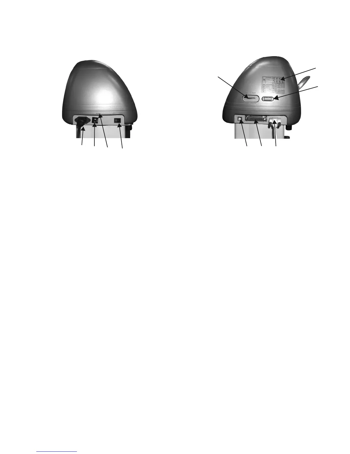
Left Hand Side (Figure 1-4)
1. AC Power Connector – Used to insert the AC power cord.
2. Fuse – Up to 3 Amps.
3. Voltage Switch – The presetting is 230 voltage. Please adjust to comply with your local standard.
4. Power Switch – On when switches to [I]; Off when switches to [O]
Right Hand Side (Figure 1-5)
5. Dip Switch label – Indicates the functions of the dip switches.
6. Dip Switch - Used for various parameter settings.
7. Pen Force Control Slider – Set the blade force here.
8. Universal Serial Bus Connector- Used in conjunction with Windows Printer Drivers to connect
the cutting plotter to a computer through a Universal Serial Bus Cable.
9. Serial Interface Connector (RS-232C) – Used to connect the cutting plotter to a computer
through a serial interface cable.
10. Parallel Interface Connector (Centronics) –Used to connect the cutting plotter to a computer
through a parallel interface cable.
This is a vinyl cutter. It is not intended to be used with windows drivers or as a printer.
Signwarehouse.com does not recommend that you use these drivers.
1. Learning About Your Cutter 1-4
Figure 1-4 Figure 1-5
1.4 Side View of Lynx
1 2 3 4
7
5
6
8 9 10
 Loading...