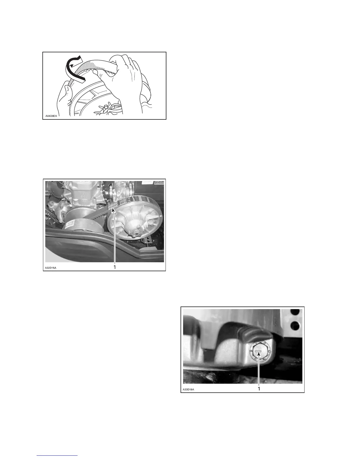
Slipthebeltoverthetopedgeofthe
sliding half, as shown.
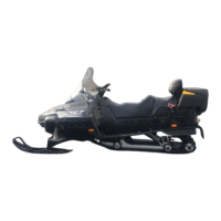
Installation all models
The maximu m drive be lt life span is
obtained when th e belt has the proper
rotation direction. Install it so the ar-
row printed on belt is pointing at fron t
of vehicle.
1. Arrow pointing at front of vehicle
CAUTION: Do not force or use tools
to pry the belt into place, as this
could cut or break the cords in the
belt.
Clean sheaves of both pulleys using
BOMBARDIER Parts Cleaner (P/N 413
711 809).
To install the drive belt, first place belt
between drive pulley sheaves. Then,
between driven pulley s heaves, finish-
ing with bottom.
Follow instructions on belt guard.
Reinstall belt guard.
When reinstallin g b e lt g uard, position
its cutaway toward front of snowm o-
bile. Refer to decal in belt guard.
NOTE: Belt guard is purposely made
slightly ove rsize to maintain te nsion on
its pins an d retainers pre ve nting un-
due noise a nd vibration. It is important
that this tension be m aintained when
reinstalling.
TRA Drive pulley
adjustment
The drive pulley is factory calibrated to
transmit maximum engine power at a
predefined RPM. refer to TECHNICAL
DATA at the end of this gu ide. F actors
such as ambient temperature, altitude
or surface condition may vary this crit-
ical engine RPM thus affecting snow -
mobile efficiency.
Calibratio n screws sh ould be adjusted
so that actual max imum engine RPM
in vehic le matches w ith the maxim um
horsepower RPM.
Use precision digital tachometer for
engine RPM adjustment.
The adjustment has an effect on high
RPM only.
To a djust, turn calibration screws.
CAUTION: Exceeding the engine
RPM results to engine damage.
Follow the adjustment sets accord-
ing technical data.
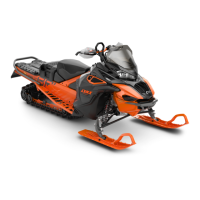
Calibration screw has a notch on top of
its head. There are 6 positions num-
bered 1 to 6.
1. Notch
62
______________________