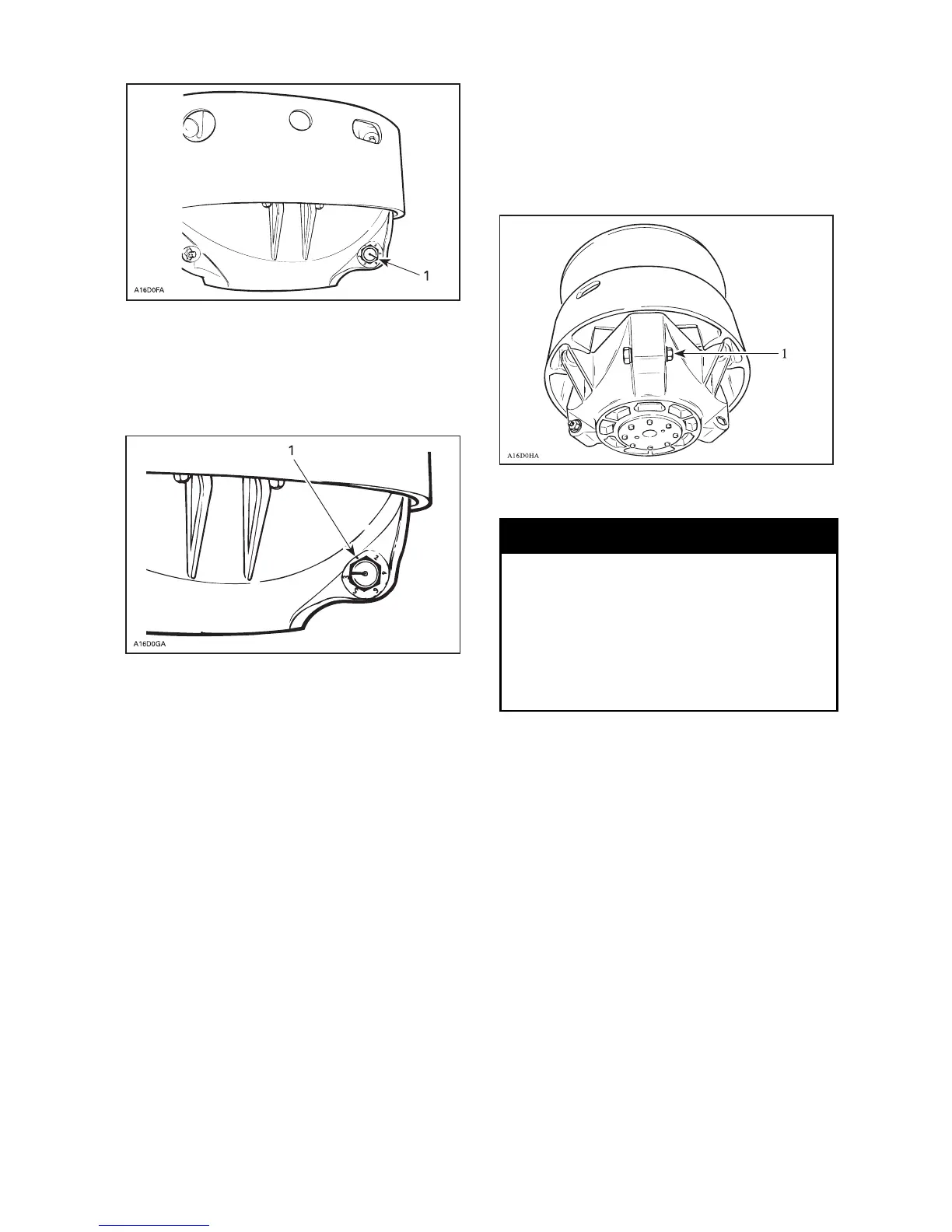
1. Notch
There are 6 positions numbered 1 to 6.
Note that in position 1 the numbe r is
substitued by a dot (due to its location
on casting).
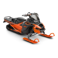
TRA DRIVE PULLEY
1. P osition 1 (not numbered)
Lower position numbers decrease en-
gine RPM in steps of 200 RPM and
higher position numbers increase it in
steps of 200 RPM.
EXAMPLE: Calibration screw is set at
position 4 and is changed to position 6:
So maximu m e ng ine RPM is increased
by 400 RPM.
Adjust as follows: (o nly if calibrations
are changed)
Loosen locking nut enough to pull cal-
ibration sc rew partially out and adjust
to desired position. Do not complete-
ly remove the locking nut. To rque nut
to 10 Nm.
CAUTION: Do not completely re-
move calibration screw otherwise
inside washer will fall off. Always
adjust all 3 calibration screw s and
make sure they are all set at the
same number.
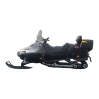
1. L oosen just enough to permit rotating
of calibrate screw
WARNING
Always reinstall belt guard. Do not
operate engine with hood open or
belt guard removed. Improper
servicing, modification or poor ad-
justment may affect drive pulley
performance and belt life. Refer
to an authorized Lynx dealer.
Drive belt condition
Inspect belt for cracks, fraying or
abnormal wear (uneven wear, wear
on one side, missing cogs, c racked
fabric). If abnormal wear is noted,
probable ca use could be pulley mis-
alignment, excessive RPM w ith frozen
track, fast sta rts w ithout warm-up pe-
riod, burred or rusty sheave, oil on
belt or distorted spare belt. Contact
an authorized Lynx dealer.
Check the drive belt width. Replace
the drive belt if width is less than
the minimum width recommended in
TECHNICAL DATA.
_____________________
63