MADE IN ITALY
17
electric modular oven
The electrical, water and thermal connection must be carried out in compliance with the
regulations in force.
Connections must be executed by skilled staff who can issue the declarations of
conformity as per law.
The room complies with all the eligibility requirements previously described and according to
current legislation
For more information, consult the attached documentation on electrical connections.
Client is responsible and take care of installation, oven power, differential magneto-thermal
switch, which needs to be :
• connected to the earth system
• installed at a reasonable distance from the oven
• visible and easily accessible
The electrical system of the room must be rated to the max power absorbed by the oven as shown
in the plate. The section of the oven feeding cables must meet the max power absorbed by the
machine as shown in the plate.
It is of fundamental importance for safety reasons that the earth system is efficiently
working.
It is strictly forbidden to modify and/or tamper safety systems or electrical circuits made by
the manufacturer.
The machine should be connected only to the main water supply and maintain the same pressure.
This connection is needed to produce steam under room pressure by means of the humidifier .
The feeding pipe diameter and the max/min pipeline pressure values are shown in the technical
data sheet of the oven (see attachment “B”).
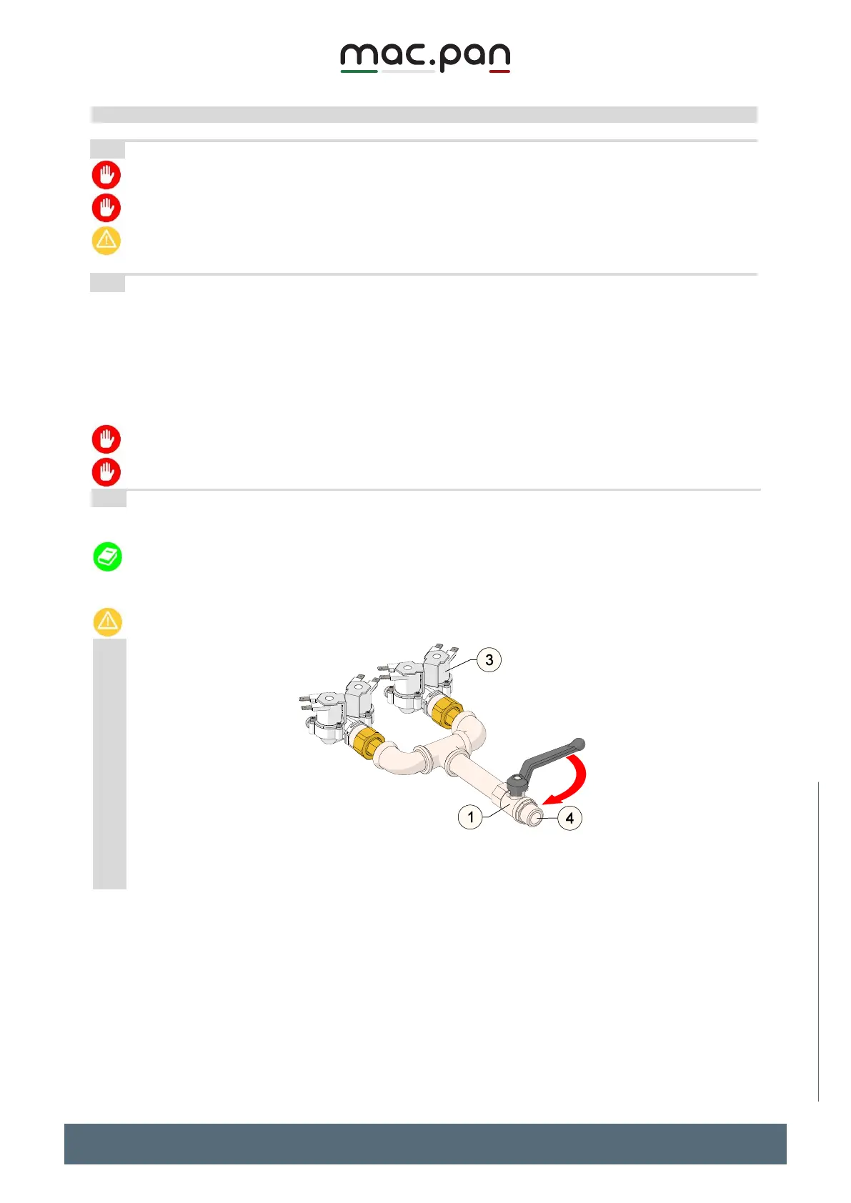
Should the pipeline pressure be higher, the shutter positioned on the oven (see figure) can be
used In case pressure is lower, a water pump unit should be installed for loading water.
It is recommended that you install a water softener on the feeding line in order to prevent the
formation of lime deposits.
FIG.6