Macurco CD-6B Manual (Rev-1.0) Eng
REV – 1.0 [34-2900-0510-2 ] 9 | Page
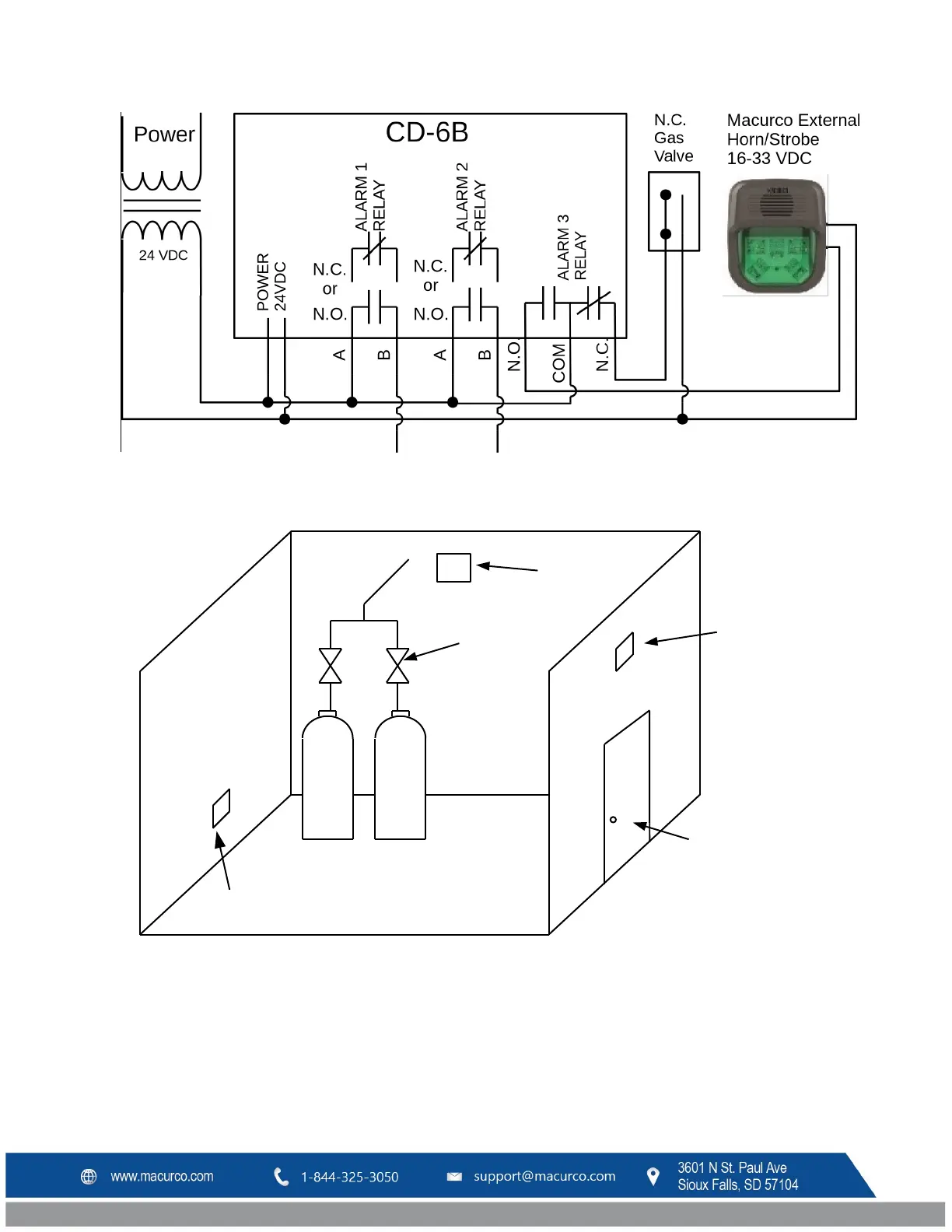
Figure 3-3 CD-6B Typical Installation wiring diagram
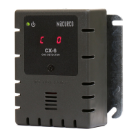
Figure 3-4 CD-6B Typical Installation Layout
NOTE: The detector should be mounted as close to the primary leak source as possible. If the tanks are inside, the
detector is typically placed as shown above. If the tanks are outside, the detector is typically placed at the
connection points of the conduit.