64
BE 57-660 Eclipse Model 700 Guided Wave Radar Transmitter
3
.6.3 Probe Selection Guide
G
WR
Probe¿
Description Application Installation
D
ielectric
Range ¡➂
Temperature
Range
Max.
Pressure
V
acuum
√
Overfill
Safe
Viscosity
cP (mPa.s)
C
oaxial GWR Probes— Liquids
7zT
Standard
Temperature
Level/Interface Tank/Chamber
ε
r
1.4–100
-40 to +200 °C
(-40 to +400 °F)
70 bar
(1000 psi)
Yes Yes 500/2000
7zP
High
Pressure
Level/Interface Tank/Chamber
ε
r
1.4–100
-196 to +200 °C
(-320 to +400 °F)
431 bar
(6250 psi)
Full Yes 500/2000
Single Rod Rigid GWR Probes— Liquids
7zF
Standard
Temperature
Level Tank
ε
r
1.4–100
-40 to +200° C
(-40 to +400° F)
70 bar
(1000 psi)
Yes
No ƒ
10000
Single Cable Flexible GWR Probes— Liquids
7z1
Standard
Temperature
Level/Interface Tank
ε
r
1.4–100
-40 to +200 °C
(-40 to +400 °F)
70 bar
(1000 psi)
Yes
No ƒ
10000
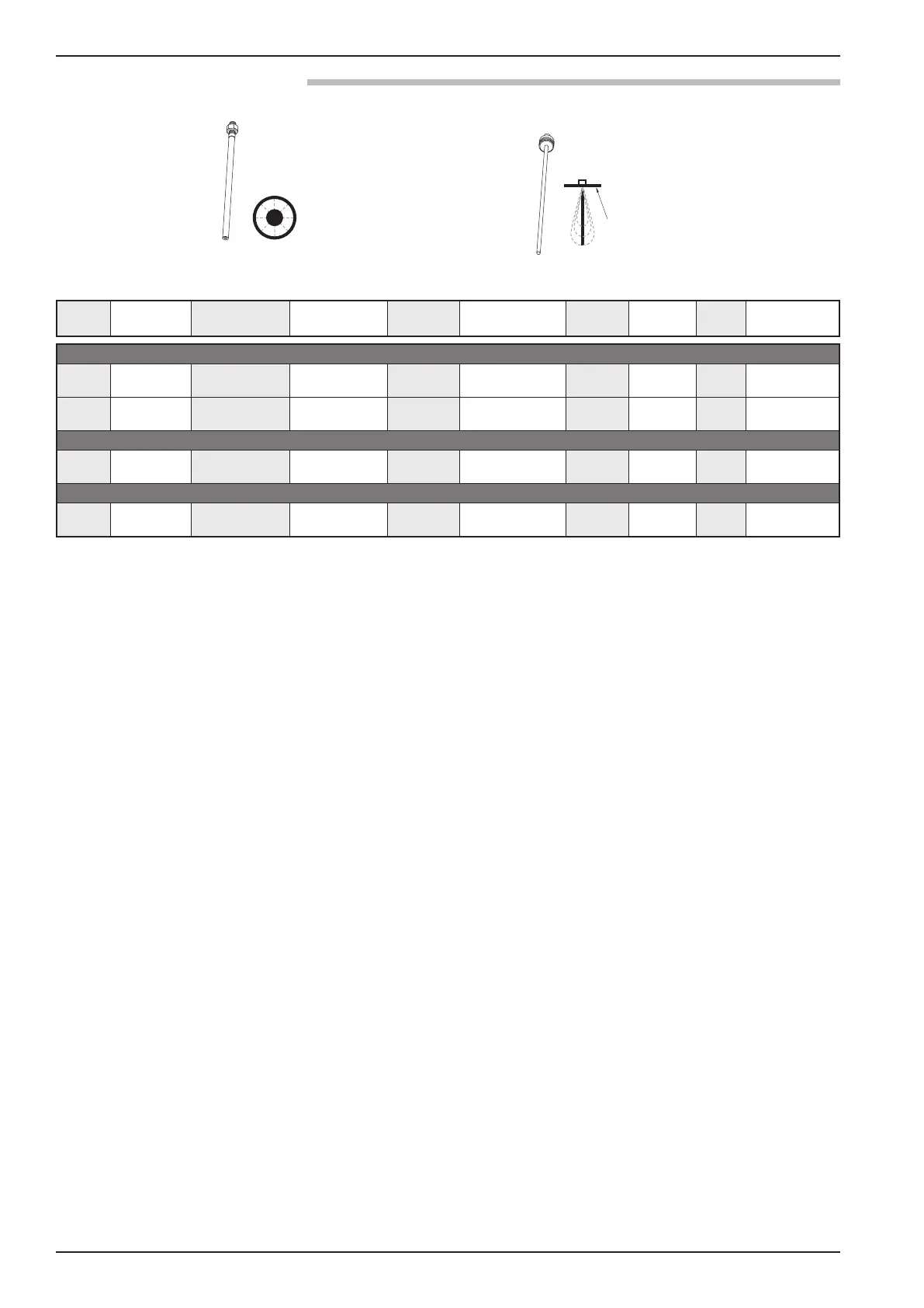
COAXIAL/CAGED GWR PROBE SINGLE ROD/CABLE PROBE
signal propagation
s
ignal propagation
end view
¿ 2
nd
digit B=English, D=Metric
¡ Minimum
ε
r
1.2 with end of probe analysis enabled.
➂
Single rod probes mounted directly into the vessel must be within 75-150 mm
(
3–6 inches) of metal tank wall to obtain minimum dielectric of 1.4, other-
wise
ε
r
min = 1.7.
√ ECLIPSE probes containing o-rings can be used for vacuum (negative
pressure) service, but only those probes with glass seals are hermetically
s
ealed to <10
-8
c
c/sec @ 1 atmosphere helium.
ƒ
Overfill capability can be achieved with software.
L
aunch Plate