65
BE 57-660 Eclipse Model 700 Guided Wave Radar Transmitter
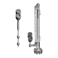
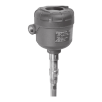
Dual-element Probes
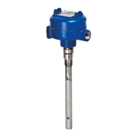
Single Rod Probes
NOTE: Transition Zone is dielectric dependent; ε
r
= dielectric permittivity. The transmitter
still operates but level reading may become nonlinear in Transition Zone.
Model
Coaxial
(7zT)
HP Coaxial
(7zP)
Materials
316/316L SS
TFE spacers,
Viton
®
O-rings
316/316L SS,
Glass Ceramic Alloy, Inconel
TFE spacers
Diameter
Small Coaxial: 8 mm (.3125") diameter rod, 10 mm (.875") diameter tube
Enlarged Coaxial: 15 mm (.6") diameter rod, 44 mm (1.75") diameter tube
Process
Connection
3/4" NPT, 1" BSP
ASME or EN flanges
3/4" NPT, 1" BSP
ASME or EN flanges
Transition Zone
(Top)
None
Transition Zone
(Bottom)
150 mm (6") @ ε
r
= 1.4
25 mm (1") @ ε
r
= 80.0
Pull Force/Tension
N/A
Model 7zF 7z1 Flexible
Materials
316/316L SS
Viton
®
O-rings
316/316L SS,
Viton
®
O-rings
(optional PFA coating)
Diameter
13 mm (0.5") 6 mm (0.25")
Blocking Distance - Top
0–45 cm (0–18")–Installation dependent (adjustable)
Process
Connection
1" NPT (7zF)
ASME or EN flange
2" NPT
ASME or EN flange
Transition Zone
(Top)
Application Dependent
Transition Zone
(Bottom)
5 mm (2") @ ε
r
>10
305 mm (12") minimum
Pull Force/Tension
N/A 9 Kg (20 lbs.)
Side Load
Not more than 7.6 cm (3") deflection at
end of 305 cm (120") probe
Cable not to exceed 5° from vertical
3
.6.4 Probe Specifications