13
57-600 Eclipse
®
Guided Wave Radar Transmitter
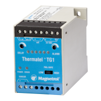
2. Ratio of Diameter: Length (A:B) is 1:1 or greater; any
ratio <1:1 (e.g., a 2"× 6" nozzle = 1:3) may require a
Blocking Distance and/or DIELECTRIC adjustment
(see Section 2.6.5.2 Measurement Type: Level and
Volume).
3. No pipe reducers (restrictions) are used.
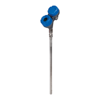
• Probe is kept away from conductive objects to ensure proper
performance. See Probe Clearance Table below. A lower gain
(increase in DIELECTRIC setting) may be necessary to
ignore certain objects (see Section 2.6.5.4 Measurement
Type: Interface and Volume).
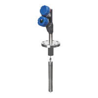
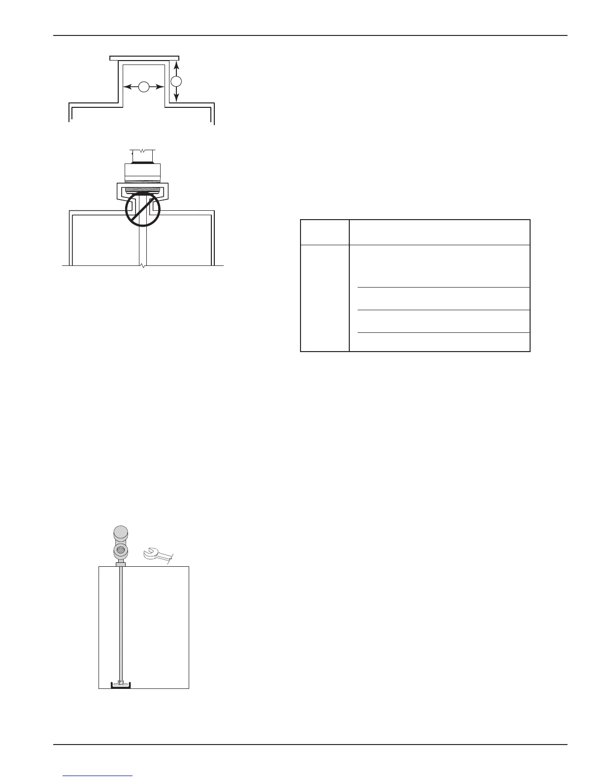
2.4.3.1 To install a Model 7xF rigid single rod probe:
➀ Make sure the process connection is at least 2" NPT or a
flanged mounting.
➁ Carefully place the probe into the vessel. Align the gasket
on flanged installations.
➂ Align the probe process connection with the threaded or
flanged mounting on the vessel.
➃ For threaded connections, tighten the hex nut of the probe
process connection. For flanged connections, tighten flange
bolts.
➄ Probe can be stabilized by placing into a non-metallic cup
or bracket at the bottom of the probe. A TFE bottom
spacer (P/N 89-9114-001) is optional for mounting into
a metallic cup or bracket.
NOTE: If the transmitter is to be installed at a later time, do not remove
the protective cap from the probe. Do not use sealing com-
pound or TFE tape on probe connection to transmitter as this
connection is sealed by a Viton
®
O-ring.
2.4.3.2 To install a Model 7x1 flexible single rod probe:
➀ Make sure the process connection is at least 2" NPT or a
flanged mounting.
➁ Carefully place the probe into the vessel. Align the gasket
on flanged installations.
Distance
to Probe Acceptable Objects
<6" Continuous, smooth, parallel conductive
surface, for example a metal tank wall;
important that probe does not touch wall
>6" <1" (25mm) diameter pipe and beams,
ladder rungs
>12" <3" (75mm) diameter pipe and beams,
concrete walls
>18" All remaining objects
PROBE CLEARANCE TABLE