LEVEL and AI OUTPUT values Basic configuration data is Reconfigure the Probe Model and/or Probe
are inaccurate. questionable. Mount, Probe Length or Level Offset.
1) Ensure the Level is accurate.
2) Verify EU_0% and EU_100% values.
Interface level has significant emulsion. Examine process to reduce/eliminate
emulsion layer.
LEVEL readings are repeatable but Configuration data does not Ensure proper Probe Model and probe length.
consistently high or low from actual accurately match probe length
by a fixed amount. or tank height. Adjust trim level value by the amount of
noted inaccuracy.
LEVEL and AI OUTPUT values Turbulence Increase the AI Block process value filter
fluctuate. time until the readings stabilize.
High Frequency connection Check Fid Spread (should be stable within
±10 counts).
LEVEL and AI OUTPUT values Lower dielectric material over higher Select Fixed Threshold option.
all reading low vs. actual. dielectric material, e.g., oil over water
Coating, clumping or buildup on probe These may be expected inaccuracies due
to affect on pulse propagation.
Dense, water based foam These may be expected inaccuracies due
to affect on pulse propagation.
Level Reading on Display is stuck at Software believes probe is flooded Check actual level. If probe is not flooded,
full scale. (level near very top of probe). Check for buildup or obstructions near top
of probe. Select higher dielectric range.
Check for condensation in probe
connection. Add Blocking Distance.
LEVEL and AI OUTPUT values Possible configuration issue 1) Increase Blocking Distance
values all at maximum level. with single rod probe 2) Increase Dielectric Range
LEVEL and AI OUTPUT values Possible obstruction in tank 1) Increase Dielectric Range until
reading high vs. actual. affecting single rod probe obstruction is ignored
2) Relocate probe away from obstruction
LEVEL value reading high when Transmitter loose or disconnected Ensure transmitter connected securely
should be zero. from probe to probe.
NOTE: When consulting the factory concerning improper operation, use proper tables on Pages 54-55. Enter all data when transmitter
is working CORRECTLY or INCORRECTLY.
7.0 Reference Information
7.1 Troubleshooting
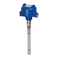
The Eclipse transmitter is designed and engineered for
trouble-free operation over a wide range of operating
conditions. Common transmitter problems are discussed
in terms of their symptoms and recommended corrective
actions. Information on how to handle material buildup
on the probe is also provided in this section.
WARNING!
E
xplosion hazard. Do not connect or
disconnect equipment unless power
has been switched off or the area is
known to be non-hazardous.
40
57-640 Eclipse Guided Wave Radar Transmitter - FOUNDATION fieldbus
™