5.0 Model 705 Menu: Step by Step Procedures
The following table describes the software menu displayed
by the Eclipse FOUNDATION fieldbus
™
transmitter for “Level
Only” measurement. Use this table as a step by step guide
to configure the transmitter.
The second column presents the menus shown on the trans-
mitter display. The displays are in the order they would
appear if the arrow keys were used to scroll through the
menu. The numbers on the first column are not shown in
the display. They are only provided as reference.
The fourth column provides the actions to take when con-
figuring the transmitter. Additional information or an expla-
nation of an action is given in the fifth column. (Shaded
sections are factory menu items).
5.1 Measurement Type: Level Only
*Status*
*Level*
*AI1Lvl*
None Transmitter Display MeasType = Lvl Only
Level
xxx.x lu
None Transmitter Display All MeasType selections
AI1 Lvl
xx.x lu
None Transmitter Display All MeasType selections
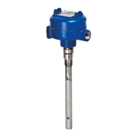
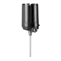
PrbModel
(select)
User
the type of probe used
Select from
PrbMount
(select)
User
the type of probe
mounting
from NPT, BSP or Flange
MeasType
(select)
User
type of measurement
from Lvl Only, Lvl&Vol, Intrface,
Ifc&Vol
SnsrUnit
(select)
User
the Sensor units from cm, inches, feet, meters
Probe Ln
xxx.x su
User
the exact length
of the probe
11.8 to 900 in (30 to 2286 cm)
Lvl Ofst
xxx.x plu
User
desired Level reading when probe
is dry
-90 to 300 in (-228.6 to 762 cm)
Senstvty
xxx
Superuser or
user
gain value upward or downward
to sense liquid surface
(Superuser password required for dual
element probes.)
BlockDis
xx.x su
User
distance below reference point
where level is not sensed
-99.9 to 2286 cm (-39.3 to 900 in)
SftyZone
(select)
User
behavior when level is sensed in
safety zone
Off, On, Latch
35
57-640 Eclipse Guided Wave Radar Transmitter - FOUNDATION fieldbus
™