!!
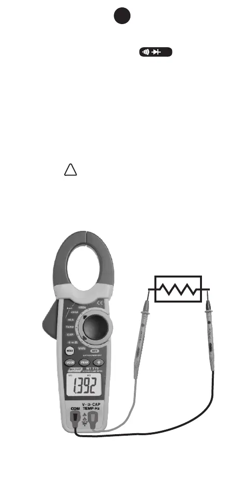
12. RESISTANCE MEASUREMENT
1. Set the function switch to range
position. The meter automatically defaults to
resistance range.
2. Insert the red test lead into the “V Ω TEMP HZ”
input terminal and the black lead to the “COM”
terminal.
3. Connect the other end of the test leads to the
circuit or component under test. Take the
reading on the display.
Note: • The meter is set to default to “Auto
Range” mode.
• WARNING before attempting to
make a resistance measurement, ensure
there is no voltage present on the circuit
under test.
Resistor
11
Ω