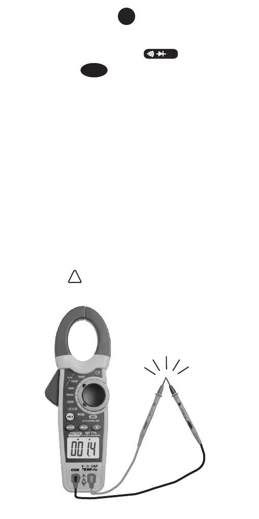
17. CONTINUITY TESTING
1. Set the function switch to range
position.
2. Press the button to select the Continuity
Test range. The meter automatically defaults to
Resistance.
3. Insert the red test lead into the “V Ω TEMP HZ”
input terminal and the black lead to the “COM”
terminal.
4. Short the tip of the test leads and make sure the
display reads “0” and the buzzer beeps.
5. Connect the tip of the test leads to the circuit or
component under test. The display reads the
resistance and the buzzer beeps when the
reading is not more than about 35Ω.
Note: • Using resistance and continuity function
in a live circuit will produce false results and
may damage the instrument.
• In many cases the suspicious
components must be disconnected from the
circuit under test to obtain accurate
results
• WARNING before attempting to
make a test, ensure there is no voltage
present on the circuit. .
MODE
Buzzer Sounds
16
!!
Ω