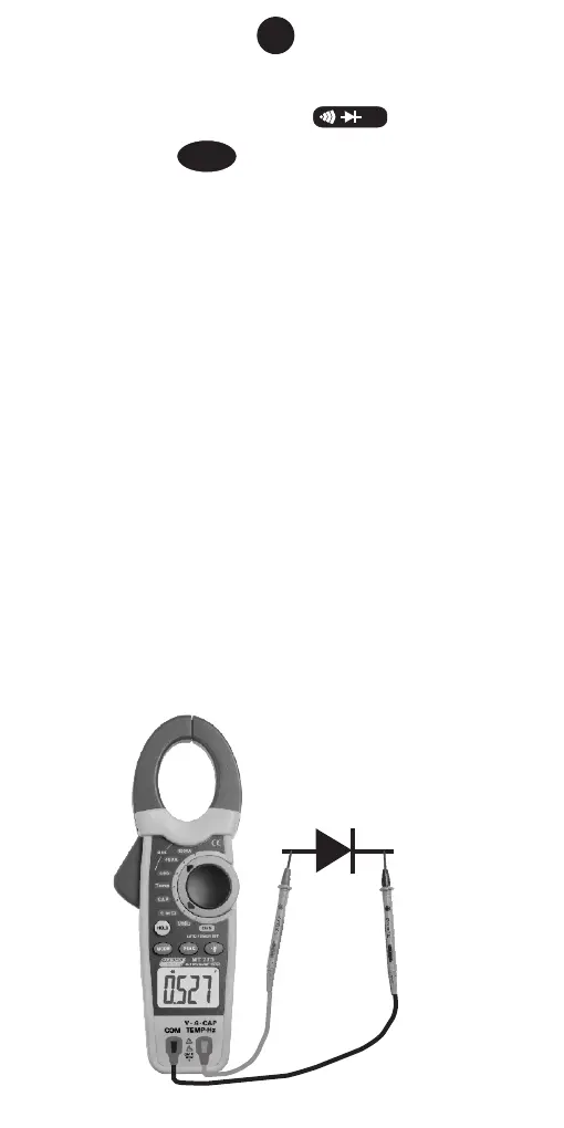
16. DIODE TEST
1. Set the function switch to range
position.
2. Press the button to select the Diode
Test range. The meter automatically defaults to
Resistance.
3. Insert the red test lead into the “V Ω TEMP HZ”
input terminal and the black lead to the “COM”
terminal.
4. Connect the other end of the test leads to the
component under test. Read the display.
Note:• Use the diode test to check diodes,
Transistors, silicon controlled rectifiers
(SCR’s) and other semiconductor devices.
• The test sends a current through a
semiconductor junction, then measures
the junction’s voltage drop.
• Normal forward voltage drop (forward bias)
for a good silicon diode is between 0.4V to
0.9V. A reading higher than that indicates
a leaky (defective) diode. A zero reading
indicates a shorted diode.
• Reverse the test leads connection (reverse
bias) across the diode. The display shows
“OL” if the diode is good. Any other
readings indicate the diode is shorted or
resistive (defective).
MODE
Ω
Diode
15