3.9: Module Signals Control
Rev 2 10/21/19 25 41113427
3.9 Module Signals Control
The mangOH Yellow uses a multi-function switch (SW403) to control specific signals.
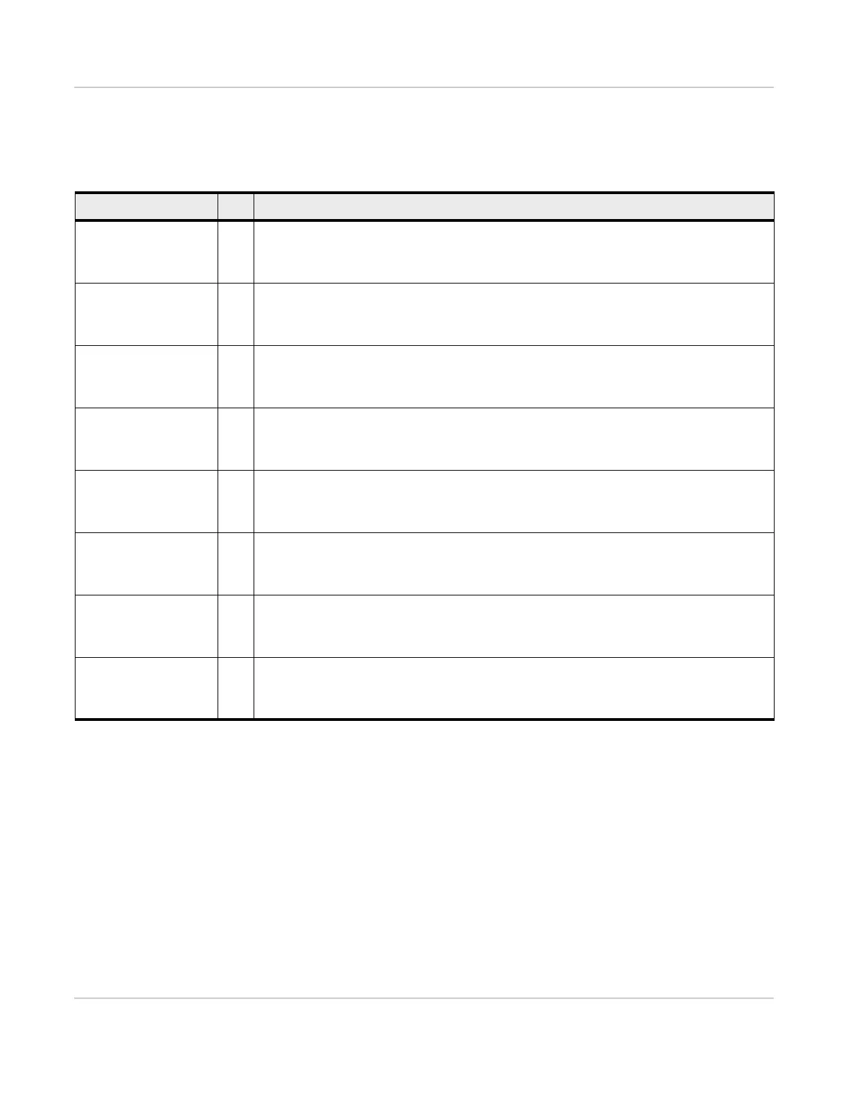
Table 3-6: SW403—Module Signals Control
Signal Dip Dip switch position / State
HL78_MODE_ON 1
Module type installed:
• ON—HL78 (Note: HL78 UART0 signals carried on CF3 socket’s UIM2 pins.)
• OFF—WP
TP1_BOOT 2
CF3 module’s TP1 (boot) signal
• ON—Stop boot process at primary bootloader and enter recovery programming mode
• OFF—Boot normally
BUCK_DISABLE_N 3
Buck converter state, controls which components receive power
• ON—Converter is off. Only CF3 module receives power.
• OFF—Converter is on. All components receive power.
W_DISABLE_N 4
Radio state
• ON—Disable
• OFF—Enable
CELL_ANT_CNTR 5
Main antenna to use
• ON—External (use Main u.FL connector)
• OFF—Integrated
WIFI_ANT_CNTR 6
Wi-Fi antenna to use
• ON—External (use WiFi u.FL connector)
• OFF—Integrated
GPS_ANT_CNTR 7
GPS antenna to use
• ON—External (use GPS u.FL connector)
• OFF—Integrated
SDIO_SEL2 8
SD interface source
• ON—microSD card/IoT card
• OFF—Wi-Fi module
 Loading...