D -
D - HYDRAULIC ATTHYDRAULIC ATTACHMENT AND ACHMENT AND HYDRAULIC LOCKING (OPTION)HYDRAULIC LOCKING (OPTION)
TAKING UP AN ATTACHMENTTAKING UP AN ATTACHMENT
-- Ensure that the attachment is in a Ensure that the attachment is in a position facilitating the locking to the carriage. If it isposition facilitating the locking to the carriage. If it is
not correctly oriented, take the necessary precautions in order to move it safely.not correctly oriented, take the necessary precautions in order to move it safely.
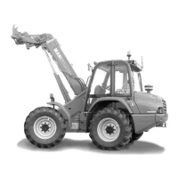
- Check that the rods on the locking cylinder are retracted (fig. A).- Check that the rods on the locking cylinder are retracted (fig. A).
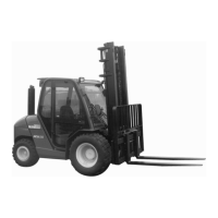
-- Place the lift truck with the jib fully lowered in front of and parallel to the Place the lift truck with the jib fully lowered in front of and parallel to the attachment, tiltattachment, tilt
the carriage forwards (fig. B).the carriage forwards (fig. B).
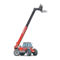
-- Bring the carriage under the locking tube of the attBring the carriage under the locking tube of the attachment, slightly lift the jib, incline theachment, slightly lift the jib, incline the
carriage backwards in order to position the attachment (fig. C).carriage backwards in order to position the attachment (fig. C).
- Lift the attachment off the ground to facilitate locking.- Lift the attachment off the ground to facilitate locking.
HYDRAULIC LOCKING AND CONNECTING THE ATTACHMENTHYDRAULIC LOCKING AND CONNECTING THE ATTACHMENT
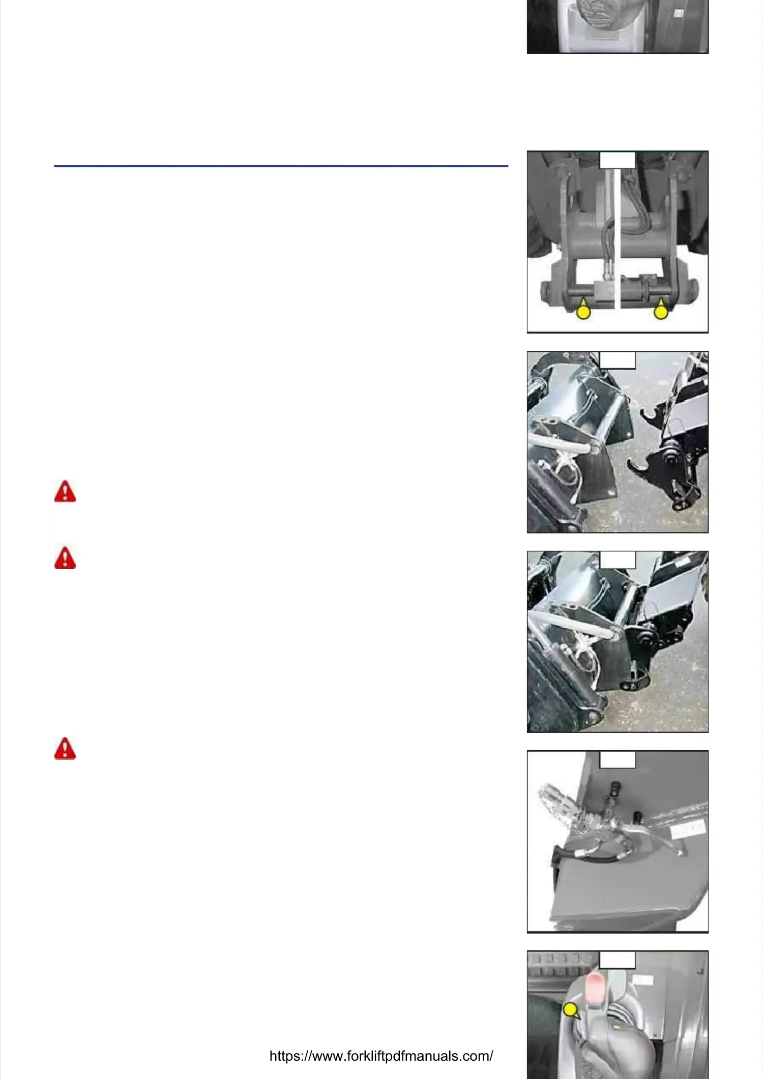
-- Put the valve in position A (fig. D), that is to sPut the valve in position A (fig. D), that is to say, thay, the hydraulic circuit of the attachmente hydraulic circuit of the attachment
locking open.locking open.
-- Switch button 1 (fig. E) of Switch button 1 (fig. E) of the distributor lever forwards to completely lock the attachmentthe distributor lever forwards to completely lock the attachment
on the carriage.on the carriage.
- Stop the I.C. engine and keep the ignition on the lift truck.- Stop the I.C. engine and keep the ignition on the lift truck.
-- Remove the pressure of the hydraulic circuit by operating switch 1 (fig. E) oRemove the pressure of the hydraulic circuit by operating switch 1 (fig. E) on the distributorn the distributor
lever backwards and forwards 4 or 5 times.lever backwards and forwards 4 or 5 times.
-- Connect the rapid connectors Connect the rapid connectors according to the logic of the attachaccording to the logic of the attachment’s hydraulicment’s hydraulic
movements.movements.
Make sure that the rapid Make sure that the rapid connectors are clean and protect the holes which are connectors are clean and protect the holes which are not used, with the capsnot used, with the caps
provided.provided.
-- Close the valve in position B (fig. D), that is to sayClose the valve in position B (fig. D), that is to say, the hydraulic circuit of the attachment, the hydraulic circuit of the attachment
locking closed.locking closed.
Always close the valve in position B (fig. D) after locking the attachment, in order to avoid accidentalAlways close the valve in position B (fig. D) after locking the attachment, in order to avoid accidental
unlocking and to use unlocking and to use the attachment completely safely.the attachment completely safely.
HYDRAULIC RELEASING AND DISCONNECTING THE ATTACHMENTHYDRAULIC RELEASING AND DISCONNECTING THE ATTACHMENT
- Close the attachment.- Close the attachment.
-- Put the valve in position A (fig. D), that is to sPut the valve in position A (fig. D), that is to say, thay, the hydraulic circuit of the attachmente hydraulic circuit of the attachment
locking open.locking open.
-- Switch button 1 (fig. E) of the distributoSwitch button 1 (fig. E) of the distributor lever backwards to completely release ther lever backwards to completely release the
attachment.attachment.
- Stop the I.C. engine and keep the ignition on the lift truck.- Stop the I.C. engine and keep the ignition on the lift truck.
-- Remove the pressure of the hydraulic circuit by operating switch 1 (fig. E) oRemove the pressure of the hydraulic circuit by operating switch 1 (fig. E) on the distributorn the distributor
lever backwards and forwards 4 or 5 times.lever backwards and forwards 4 or 5 times.
- Disconnect the rapid connectors of the attachment.- Disconnect the rapid connectors of the attachment.
Make sure that the rapid Make sure that the rapid connectors are clean and protect the holes which are connectors are clean and protect the holes which are not used, with the capsnot used, with the caps
provided.provided.
LAYING AN ATTACHMENTLAYING AN ATTACHMENT
-- Proceed in the reverse order of paragraph TAKING UP AN AProceed in the reverse order of paragraph TAKING UP AN ATTACHMENT while making sureTTACHMENT while making sure
you place the attachment flat on the you place the attachment flat on the ground and in closed position.ground and in closed position.
AA
BB
CC
DD
EE
11
 Loading...