Manitowoc Published 07-23-15, Control # 078-03 4-55
31000 LUFFING JIB OPERATOR MANUAL SET-UP AND INSTALLATION
58
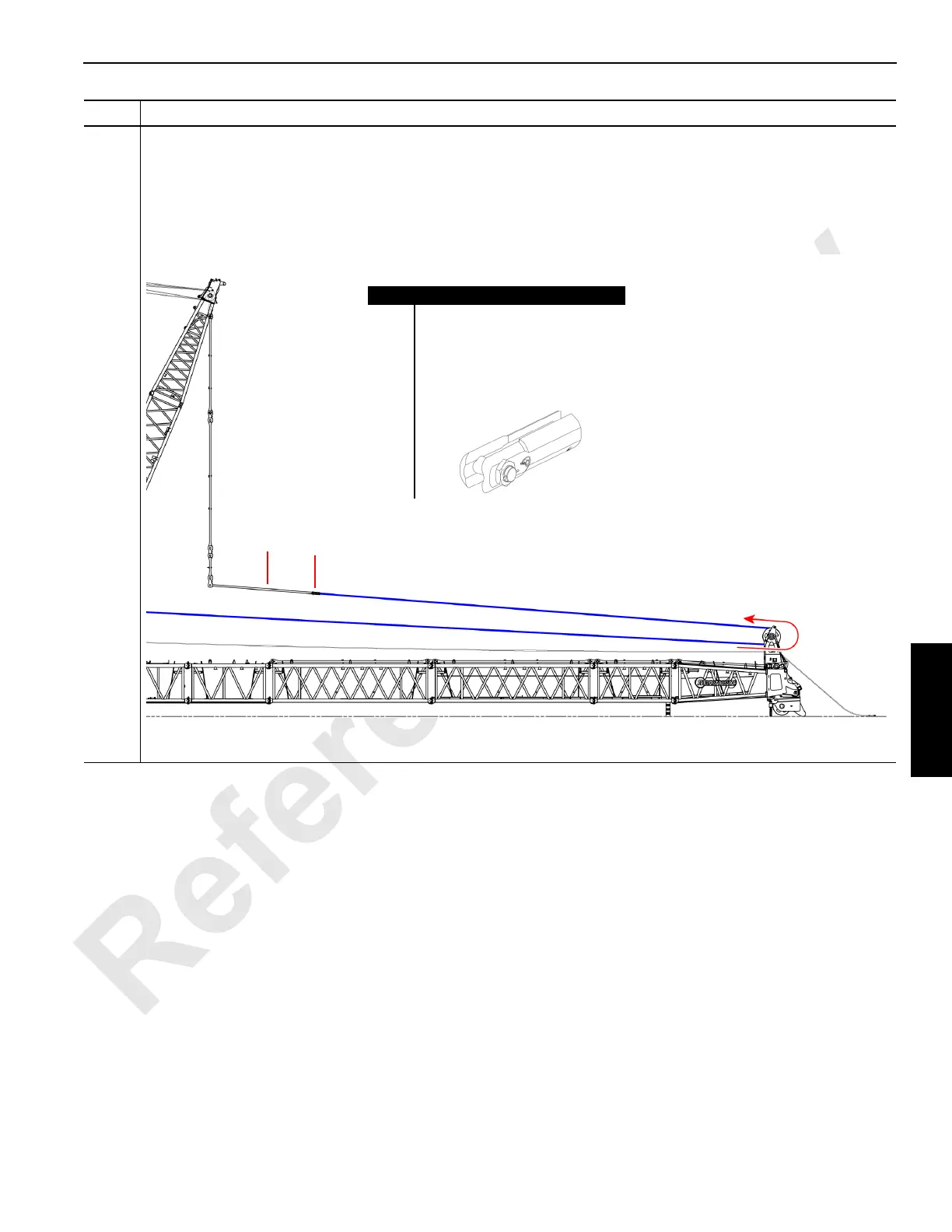
Information below from drawing A19443, Sheet 25:
• With Drum 1 (A) or Drum 3 (B) reeved to the jib top wire rope guide, reeve the other line — Drum 3 (B) or Drum
1 (A) — from the bottom to the top on the wire rope guide upper sheave (C) and towards the suspended strap
(D) links.
• Relocate the pin/collar/pin connection from the end of the 12M insert straps to the suspended straps (D).
• Attach a sling to the Drum 3 (B) or Drum 1 (A) load hoist rope socket.
Step Action
FIGURE 4-58
A (or B)
Item Description
A Drum 1 main load hoist line.
B Drum 3 whip/auxiliary load line.
C Wire rope guide top sheave.
D Suspended straps.
E Sling.
F Socket.
B (or A)
C
D
E
F