SET-UP AND INSTALLATION 31000 LUFFING JIB OPERATOR MANUAL
4-60 Published 07-23-15, Control # 078-03
66
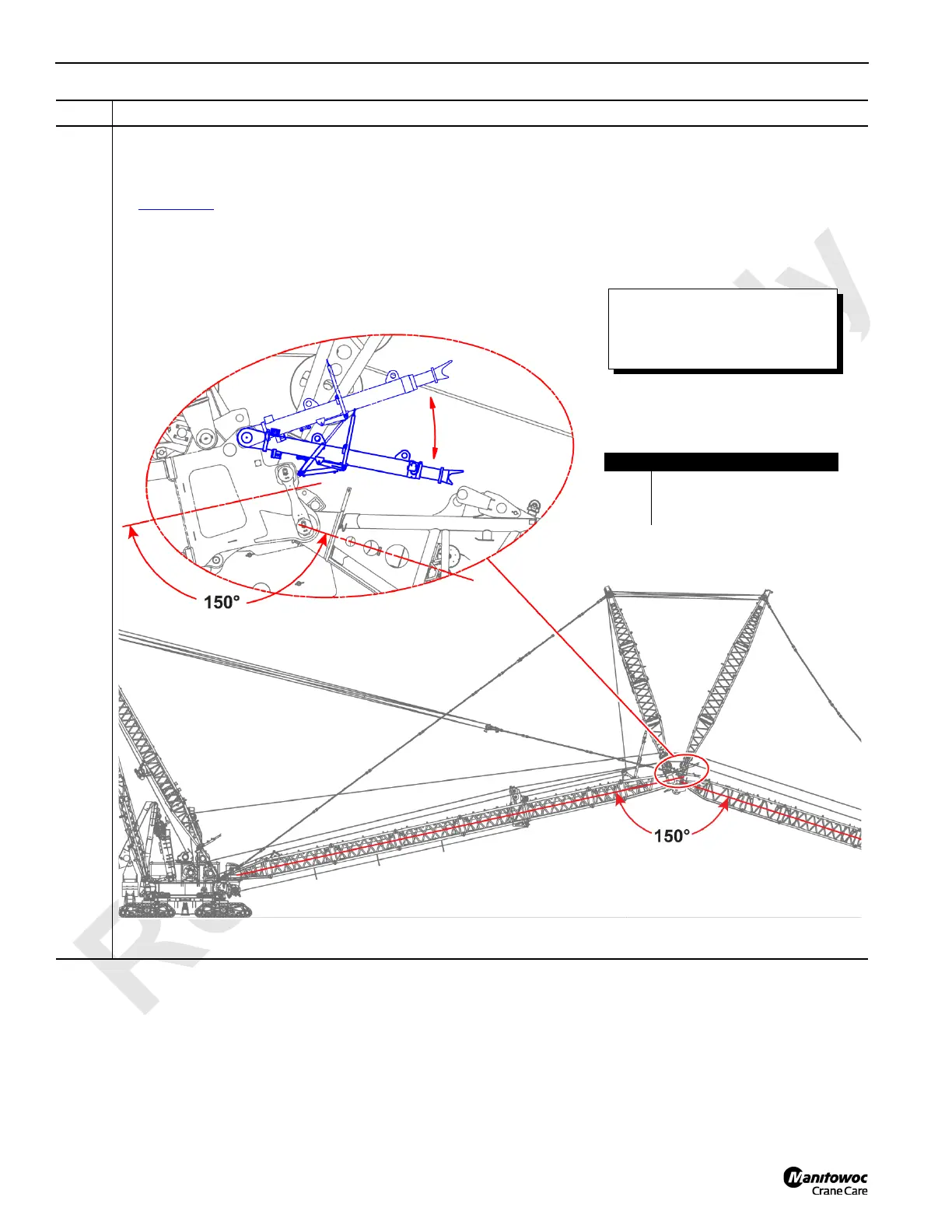
Information below from drawing A19443, Sheet 26:
Once the boom-to-luffing jib angle is 150°, retract each jib stop support cylinder, one at a time:
• Connect the Arctic 15 hydraulic hoses from the Portable Power Unit to either jib stop cylinder (A) as shown in
Figure 4-50
.
• Then retract the jib stop cylinder to lower it from the erecting position (B) to the operating position (C).
• Repeat the steps for the other jib stop cylinder.
Step Action
FIGURE 4-63
Item Description
A Jib stop cylinder.
B Erecting position.
C Operating position.
A
A
B
C
The boom, luffing jib, and jib stop
will be damaged if the jib stop
cylinders are not lowered to the
operating as instructed.