Manitowoc Published 07-23-15, Control # 078-03 4-61
31000 LUFFING JIB OPERATOR MANUAL SET-UP AND INSTALLATION
67
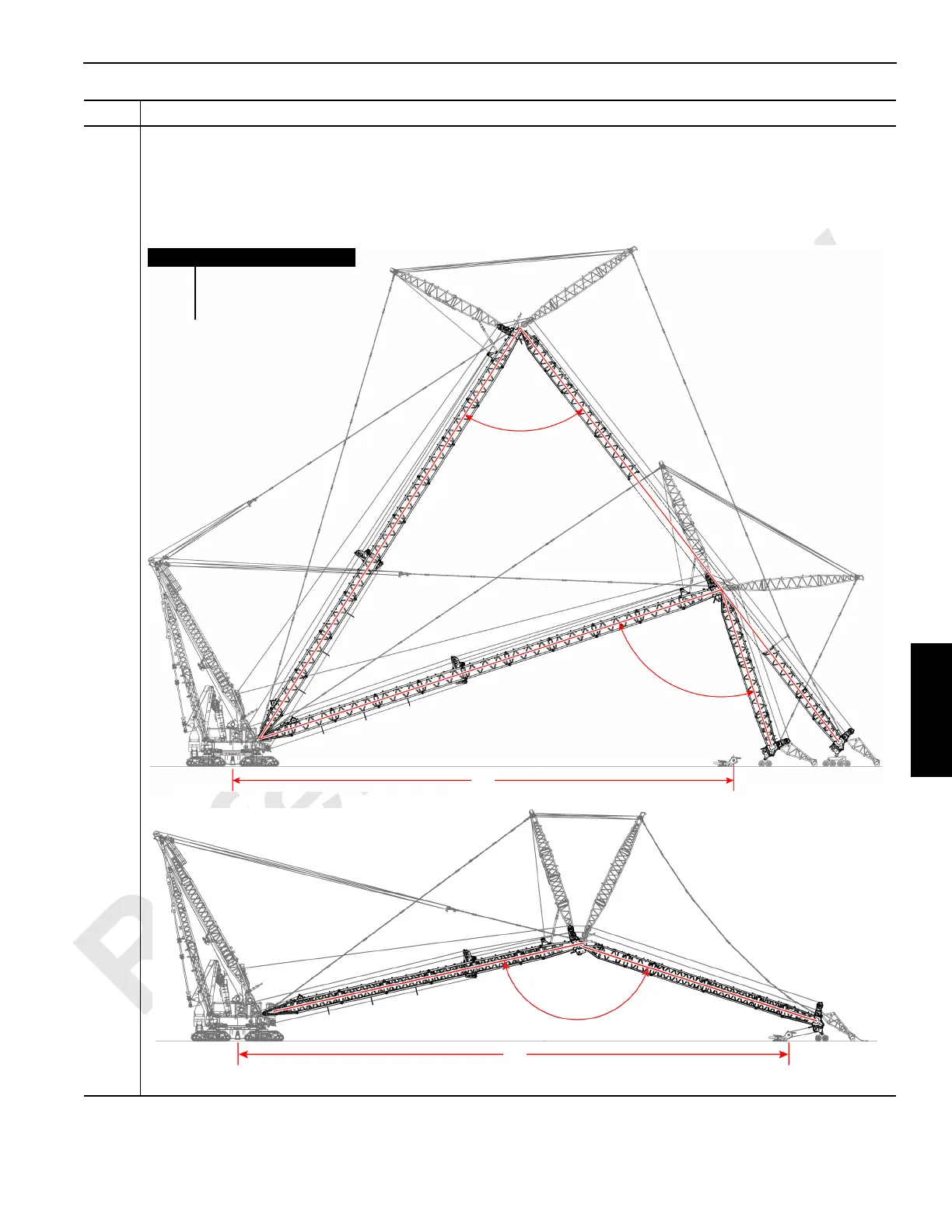
Information below from drawing A19443, Sheet 26 and 27:
• Raise the boom to the proper boom-to-luffing jib included angle (A) — 70°, 90°, or 150° — specified in the luffing
jib raising/lowering procedure charts.
• In order to reeve the hook block (B), locate the hook block the distance (C) within the luffing jib capacity chart at
lift off.
Step Action
FIGURE 4-64
Item Description
A Boom-to-luffing jib angle.
B Hook block.
C Hook block distance.
A
70°
A
90°
A
150°
B
B
C
C
Long boom/Long Jib
configuration shown
Long boom/Short Jib
configuration shown