SET-UP AND INSTALLATION 31000 LUFFING JIB OPERATOR MANUAL
4-62 Published 07-23-15, Control # 078-03
68
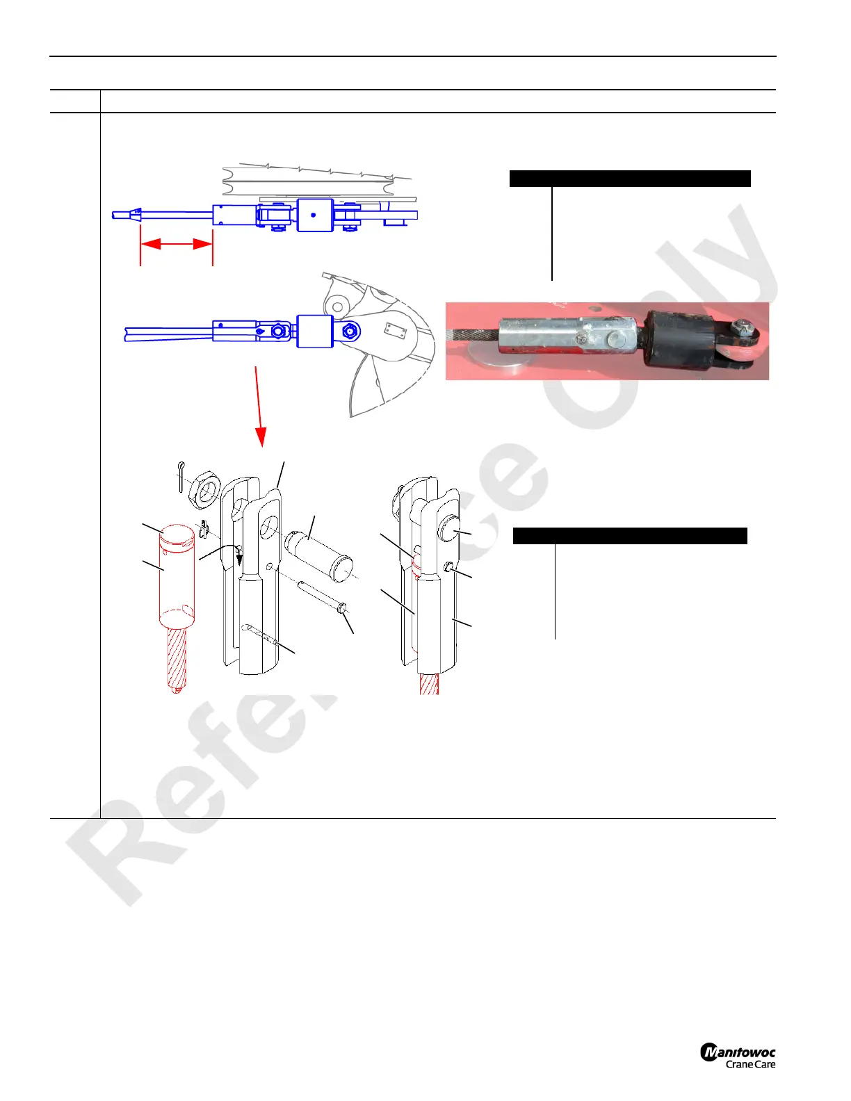
Information below from drawing A19443, Sheet 26:
Temporarily remove the link swivel (A) and button socket (B) from the lower boom point dead end lug (C).
Step Action
A
A
B
B
A
B
C
FIGURE 4-65
Item Description
A Link swivel.
B Button socket.
C Lower boom point dead end lug.
D 800 mm (23.6 inches).
E 50 mm wire rope (Drum 1 and/or
Drum 2, and Drum 3).
D
E
1
2
3
5
6
1
2
4
• Button cover (4) must be attached to button (3).
• Flat on button (3) must be against roll pin (5).
• Be sure to install locking pin (6) after button is inserted in socket.
6
Item Description
1 Bolt, Nut, and Cotter Pin
2 Button Socket
3 Button (on load line)
4 Button Cover
5 Roll Pin
6 Locking Pin with Quick-Release Pin
4
3