SET-UP AND INSTALLATION 31000 LUFFING JIB OPERATOR MANUAL
4-64 Published 07-23-15, Control # 078-03
70
Information below from drawing A19443, Sheet 26:
Reeve the 19 mm Drum 6 winch wire rope (A) through the lower boom point assembly (B) and the hook block (C)
per the reeving diagrams as indicated on the selected hook block:
• Place the hook block main equalizer (D) in a 45° position with the connector beam (E) parallel to the main eye
(F) which shall be tied up to the bolt just above the eye with a strap to prevent the eye from swinging around
during laying down and standing up after reeving.
• Position the hook block main equalizer sheaves (G) in line with the lower boom point sheaves (H).
• Position the luffing jib (with or without a dolly) to allow for adequate rigging of 50 mm wire rope with clearance at
the connector beam.
NOTE: When reeving the hook block and the luffing jib is positioned in a dolly, chock the dolly wheels for stability.
NOTE: The optional upper boom point shall not be preinstalled per Figure 4-77
if the boom-to-luffing jib angle
configuration is either 70° or 90° and the luffing jib top is positioned on the ground or blocking instead of
on a dolly.
71
Information below from drawing A19443, Sheet 26:
Connect the dead end to the 50 mm wire rope:
• When the reeving of the hook block is complete, remove the shackles and snatch block from the lower boom
point dead end lug (see Figure 4-66
).
• Reattach the link swivel and button socket from the lower boom point dead end lug that were removed in
Figure 4-65
.
• Assemble the 50 mm wire rope end into the button socket shown in Figure 4-65
. Then place loose components
into a stowage box.
72
• If an upper boom point will be attached after hook block reeving, then go to Upper Boom Point Installation —
Method 2 on page 4-74.
• Otherwise, this complete the #91 luffing jib installation.
Step Action
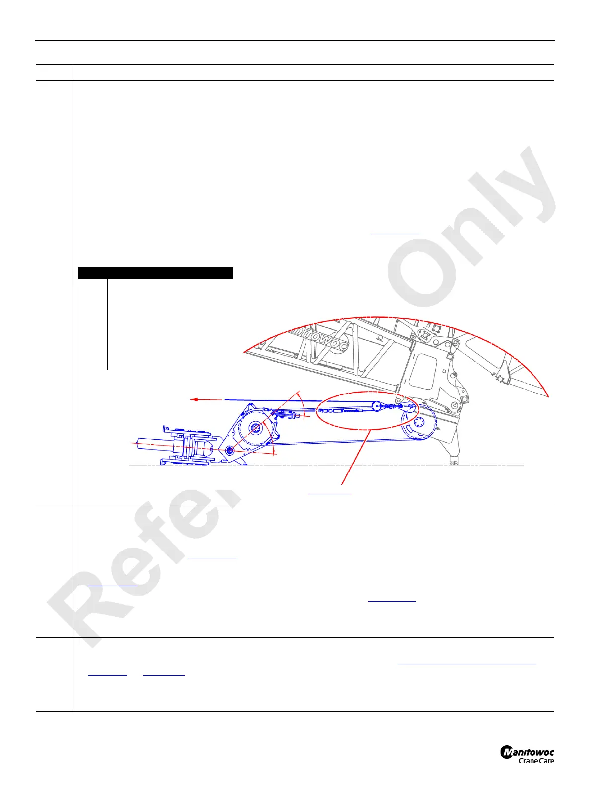
FIGURE 4-67
Item Description
A Drum 6 winch wire rope.
B Lower boom point assembly.
C Hook block.
D Hook block main equalizer.
E Connector beam.
F Main eye.
G Main equalizer sheaves.
H Lower boom point sheaves.
A
B
C
E
45°
D
45°
See Figure 4-66
for details.
F
G
H