GROVE Published 10-21-2010, Control# 198-04 4-47
5540F/YB5515 SERVICE MANUAL HYDRAULIC SYSTEM
Complete Valve Assembly
1. Layout the valve components on a clean, flat working
surface.
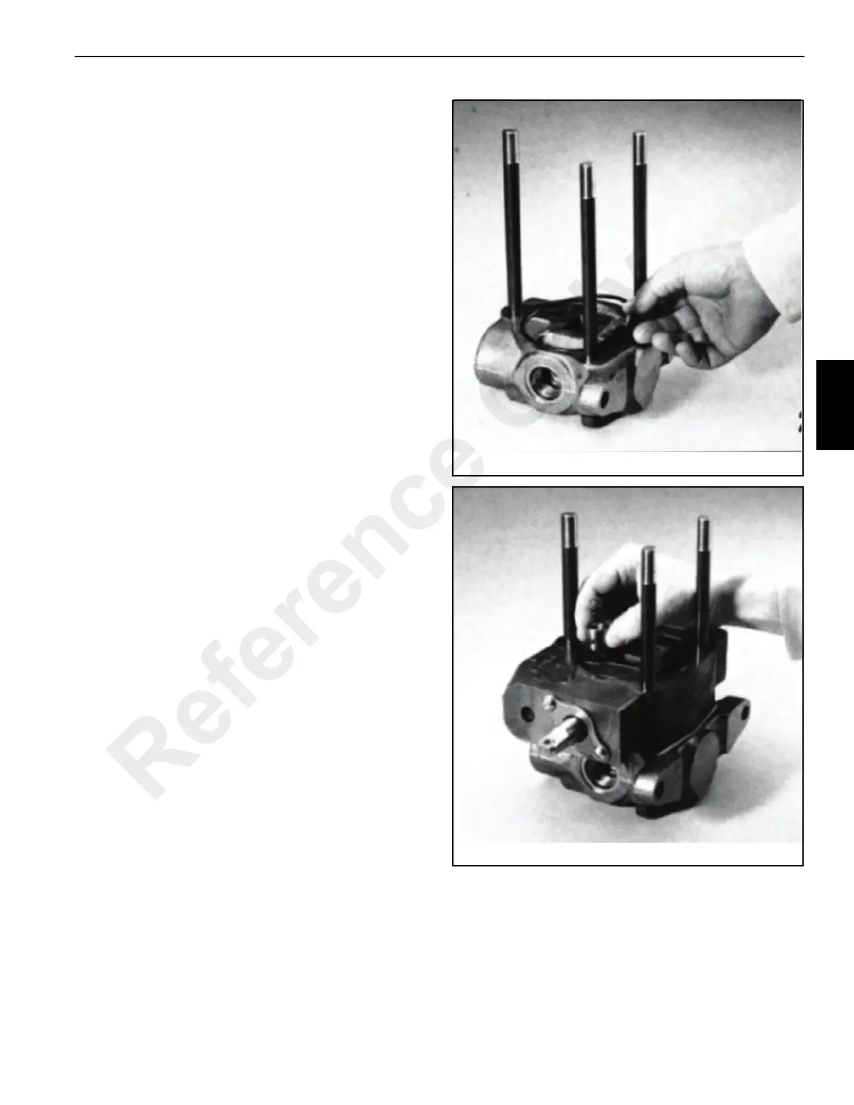
2. Assemble tie rod nuts and washers to one end of each
tie rod 17 Figure 4-42. Insert the tie rods through the tie
rod holes of inlet section 2. Lay the inlet section with the
tie rods facing up.
3. Place o-ring 3 in position on the face of the inlet section
Figure 4-44.
4. Place the swing pool section 5 Figure 4-42, o-ring side
up, on the inlet section 16. Position the o-ring 2
Figure 4-43 and insert load check poppet 3 and spring 4
into load check cavity Figure 4-45. Be sure the nose of
the check poppet is facing down.
5. Position mid-inlet section 6 Figure 4-42 in place.
6. Repeat step 4 above for the telescope spool section 8.
7. Repeat step 4 above for the outrigger spool sections 9.
8. Position mid-inlet sections 13 and 14 with new o-rings 3
in place.
9. Repeat step 4 above for the winch spool section 8.
10. Position mid-inlet section 15 in place.
11. Repeat step 2 above for the boom lift spool section 8.
12. Position outlet section 16 on the last spool section and
hand tighten the tie rod nuts.
13. Position the valve assembly with the mounting pads of
the end sections on the flat surface. To obtain proper
alignment of the end sections relative to the spool
sections, apply downward pressure. Snug tie rod nuts to
about 10 lb-ft (13,6 Nm). Final torque on the two 1/2 inch
nuts is 14 lb-ft (19 Nm); final torque on the 9/16 inch nut
is 33 lb-ft (45 Nm).
Main Relief and Port Relief Valves
The cartridge-type relief valves are typically of the pilot
poppet type with external adjustment. Any malfunction is
usually the result of foreign matter lodging between the
piston Figure 4-46, relief valve poppet and the check valve.
To perform service, clean the surrounding area and remove
the complete relief valve cartridge. Examine the seat in the
Reference Only

 Loading...


