ENGINE AND ENGINE SYSTEMS 5540F/YB5515 SERVICE MANUAL
6-28 Published 10-21-2010, Control# 198-04
11. Remove the air cleaner and intake hose(s).
NOTE: Have a fire extinguisher handy and know how to
use it before performing the next step.
12. Disconnect the fuel lines from the fuel tank. Plug or cap
the lines to prevent leakage. On dual fuel engines, close
the L.P. tank and disconnect L.P. hose from the filterlock
on the engine.
13. Disconnect the drive shaft(s) from the transmission. See
Section 6.
14. Disconnect the exhaust pipe from the exhaust manifold
of the engine.
15. Drain the hydraulic tank.
16. Disconnect the hydraulic hoses from the four sections of
the hydraulic pump.
17. Disconnect the suction hose from the hydraulic tank and
the hydraulic pump suction manifold.
18. Disconnect the throttle linkage from the engine.
19. Disconnect the engine ground cable from the engine or
the engine flywheel.
20. Remove the rear axle.
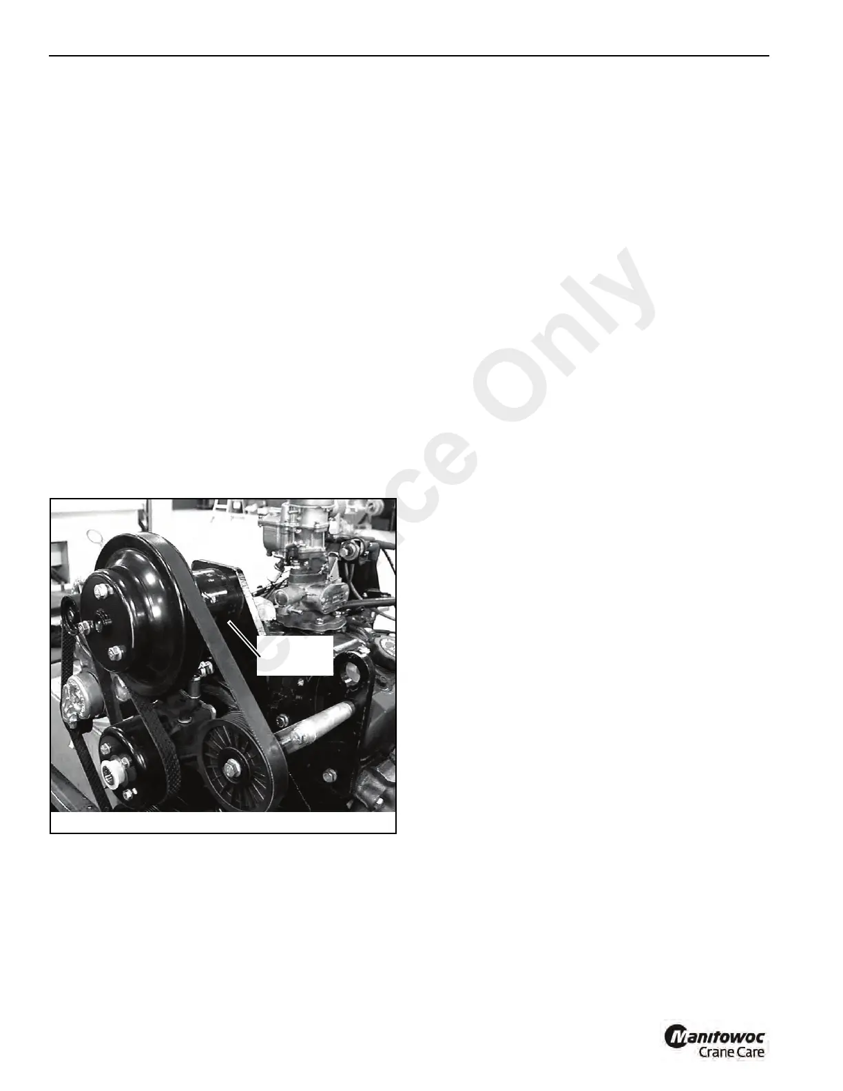
a. Support the gasoline engine by placing a sling
under the high fan mounting bracket Figure 6-23
and attach it to a hoist. Use the hoist to support the
engine while the rear axle is being removed.
b. Loosen and remove the wheel lug nuts and remove
both rear wheels.
c. Disconnect and plug the hydraulic hoses at the
steering cylinders.
d. Disconnect and cap and plug the brake hoses from
the axle.
e. Support the axle on a trolley jack.
f. Remove the front engine mounting hardware.
g. With the engine and rear axle both supported,
remove the eight bolts and flat washers securing the
engine/axle mounting bracket to the chassis.
h. Lower and remove the axle clear of the chassis.
21. Remove the rear engine support mounting bolts,
washers, rubber mounts and nuts.
22. Using a trolly jack, raise the transmission so it can be
removed out the rear of the chassis.
23. Using the hoist, slowly pull the engine and transmission
forward enough to attach a sling around the torque
converter housing. At the same time, check that all items
are free for engine removal. Attach a pull jack to the sling
and hoist.
24. Slowly, raise the engine and check that all lines and
components which can possibly cause interference with
the engine removal have been removed. Carefully lift the
engine and transmission out the rear of the frame at
about a 30° angle.
25. If a new engine is to be installed, remove all parts from
the old engine not provided with the new engine and
install them on the new engine.
Installation
1. Attach a hoist to the engine the same way removal was
accomplished.
2. Lift the engine into place over the chassis. Tilt the engine
at about a 30° angle to insert the engine into the chassis.
Lower the engine into the chassis and set the
transmission on a trolley jack. Remove the sling and pull
jack.
3. Move the engine and transmission into the chassis until
the rear mounting bolts, washers, rubber mounts and
nuts can be installed and tightened.
4. Install the rear axle.
a. Locate the rear axle under its mounting location.
Raise the axle and mounting bracket into position
and install the eight mounting bolts and flat
washers.
b. Install the front engine mounting hardware.
c. Connect the brake lines to the axle.
d. Connect the hydraulic hoses to the steering
cylinders.
5. Connect the suction hose to the hydraulic tank and the
hydraulic pump suction manifold.
FIGURE 6-23
p0106
Install sling
here
Reference Only

 Loading...


