GROVE Published 10-21-2010, Control# 198-04 7-31
5540F/YB5515 SERVICE MANUAL TRANSMISSION AND TORQUE CONVERTER
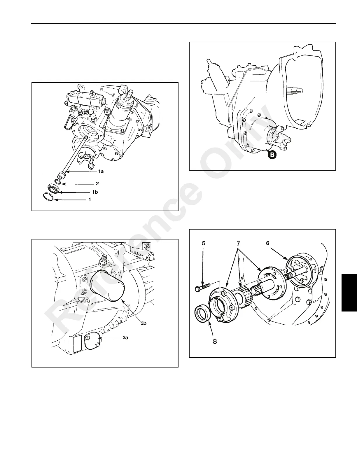
If not already removed, remove hydraulic pump from gear
box.
1. Remove the circlip (1, Figure 7-21) and then withdraw
the pump driveshaft 1a together with its bearing 1b.
2. Remove and discard the shaft sealing ring.
3. Drain the oil from the casing by removing the suction
strainer 3a. Remove and discard the oil filter 3b
(See Figure 7-22).
4. If the gearbox is fitted with a 2/4-wheel drive unit B,
remove it. See Hydraulic 2/4-Wheel Drive Unit -
Disassembly for the correct procedures
(See Figure 7-23).
5. Unscrew bolts (Figure 7-24) and withdraw pump 7.
6. Remove and discard pump sealing ring 6.
7. Separate pump 7 components. Note that the pump
components are held together with a security screw at
the rear of the assembly.
8. Remove and discard oil seal 8 from pump housing.
Position transmission vertically, standing on the face of the
torque converter housing.
9. Unscrew capscrews and remove solenoid control valve.
(9, Figure 7-25) Note the O-rings fitted around ports on
the mating face of solenoid valve body
NOTE: See Solenoid Valve for solenoid valve
disassembly and assembly procedures
Reference Only

 Loading...


