AXLES/DRIVE SHAFTS/WHEELS AND TIRES 5540F/YB5515 SERVICE MANUAL
8-22 Published 10-21-2010, Control# 198-04
15. If removal is necessary, carefully remove the brake
piston 15 from its housing. A hydraulic hand pump can
be used to force the piston out of the housing.
16. Remove and discard seals 13 and 14. Inspect the
housing bore for damage and scoring. Nicks or cuts in
the seals may be responsible for loss of brake fluid.
17. Pull off bearing carrier 8 together with outer bearing 11.
18. Pull off inner bearing 6.
19. Remove and discard combination seal 9.
NOTE: Earlier axles may have an o-ring and wear ring
installed. These parts should be discarded.
NOTE: The top and bottom trunnions are very similar
(bottom trunnion is not illustrated in Figure 8-45)
the only difference being that shims 36 are installed
to the top trunnion.
20. Mark the position of the top and bottom trunnions 34,
remove bolts 35 and remove the trunnions. Keep shims
36 with the top trunnion. Remove hub swivel 3.
NOTE: Trunnions may be removed easily and without
damage to the shims by pumping grease through
the grease fitting.
NOTE: On non-drive axles the short drive shaft will be
removed with the hub swivel.
21. Remove top and bottom trunnion seals 37 and
bearings 38.
22. Remove drive shaft 42 from the hub swivel on non-drive
axles and from the axle casing on drive axles.
23. Pry out the drive shaft outer oil seal 2.
24. Remove bearing 1 using an impulse extractor adapter.
NOTE: Steps 25 through 27 are for drive axles only.
25. Pry out drive shaft inner seal 39.
26. Remove retaining ring 40.
27. Using an impulse extractor remove bearing 41.
28. If there has been a component failure, remove all traces
of debris and clean the magnetic drain plug.
Assembly
NOTE: The top and bottom trunnions are very similar
(bottom trunnion is not illustrated in Figure 8-45,
the only difference being that shims 36 are installed
to the top trunnion.
NOTE: Steps 1 through 3 are for drive axles only.
1. Tap the drive shaft inner bearing 41 into position in the
axle casing.
2. Install retaining ring 40.
3. Install new oil seal 39. Pack grease between the lips of
the seal.
4. Tap drive shaft inner bearing 1 into position in hub swivel
3 drive shaft bore.
5. Install new oil seal 2. Pack grease between the lips of
the seal.
6. Install drive shaft 42. Take care to locate inner end into
splines of differential gears on the drive axle.
7. Press new top and bottom trunnion seals 37 into
position, followed by bearings 38.
8. Locate hub swivel 3 and install the bottom trunnion 34.
Apply Loctite 242 to threads of bottom trunnion bolts 35
and then tighten to a torque 42 lb-ft (56 Nm). Install top
trunnion 34 with normal 0.25 mm (0.010 inch) shim 36
and leave top trunnion bolts 35 finger tight.
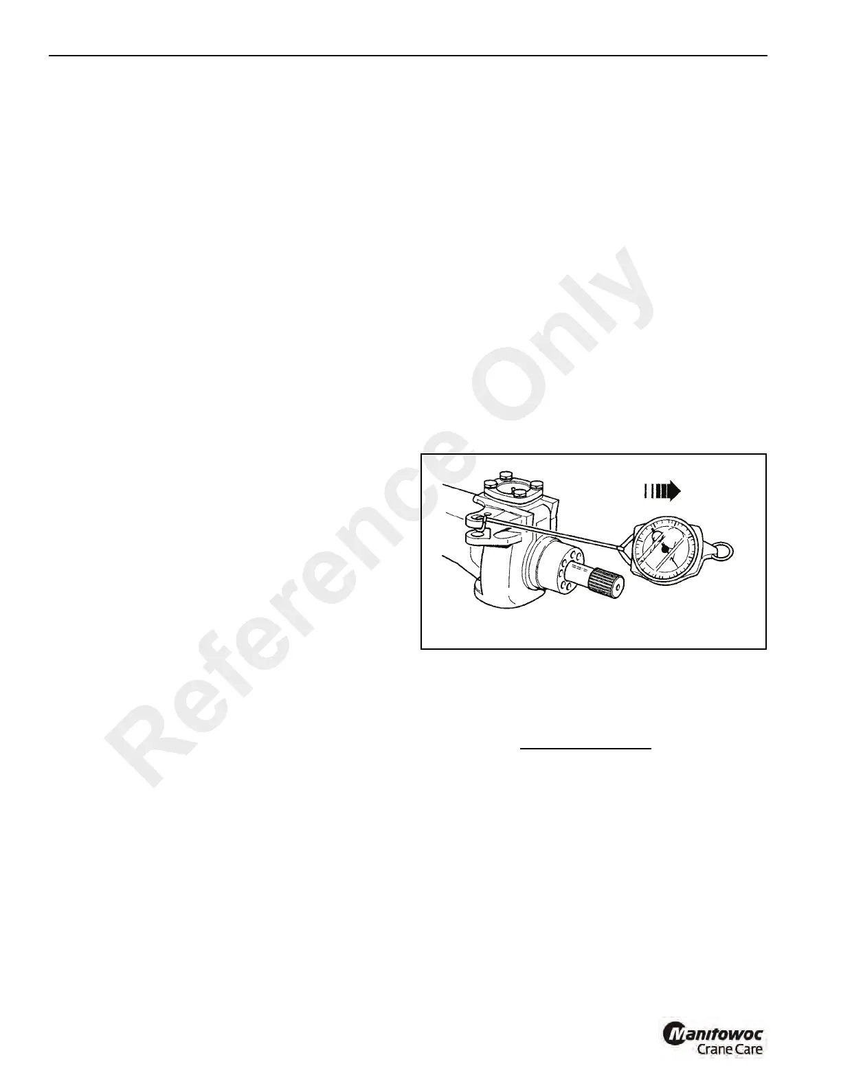
9. Attach a spring balance Figure 8-46 to track rod swivel
and turn the swivel. Tighten the top trunnion bolts 35 to
eliminate end play, but without bearing pre-load, i.e. no
increase in spring balance reading.
10. Measure the gap at the top trunnion and subtract 1 mm
(0.040 inches) to give shim thickness (bearing pre-load).
For example:
NOTE: If the gap measures 1.00 mm (0.040 inches), then
no shim is required.
NOTE: If, after installing the shims, the bearing pre-load is
not attainable, install new bearings.
11. Reinstall the top trunnion. Apply Loctite 242 to the top
trunnion bolt threads, install and tighten to a torque of
42 lb-ft (56 Nm).
12. Check the spring balance reading which should be 10 lb.
(4.5 kg) more than the reading recorded in step 9.
Gap = 1,55 mm (0.061 inches)
less = 1,00 mm (0.040 inches
Shim = 0,55 mm (0.021 inches)
Reference Only

 Loading...


