5540F/YB5515 SERVICE MANUAL
9-4 Published 10-21-2010, Control# 198-04
Low Pressure Warning Switch
The low pressure warning switch illuminates a red light on
the dash when the brake pressure goes below 850 psi
(5861 kPa). When the red light illuminates, there still is
enough pressure for brake application to stop the crane.
After which, the brake system must be checked and
repaired.
Accumulator
The accumulator is a hydro-pneumatic, piston-type
accumulator. This means that the accumulator is charged
with nitrogen and stores hydraulic fluid to a pressure of
2000 psi (13 790 kPa) for brake system usage.
Needle Valve
The needle valve is used during service of the brake system.
When closed, It shuts of the hydraulic supply from the
accumulator, holding a pressure in the accumulator. This
eliminates the need to charge the accumulator after brake
system service.
NOTE: The needle valve must in the open position for the
brake system to operate properly. If it is not open,
the charging pump will cycle every time the brake
pedal is depressed and if the crane’s engine stops
there may not be enough pressure to stop the
crane.
Brake Modulating Valve
The brake modulating valve is a closed-center spool design.
When the valve is in no-applied position, brake port, A
Figure 9-1 is open to tank port T. As the valve is initially
actuated, tank port T is closed off from brake port T.
Additional actuation opens pressure port P to brake port A.
More input force will increase the pressure to brake port A
until actuation effort and hydraulic reaction forces are
balanced. When actuation is released, the valve returns to its
non-applied position.
Brake Light Switch
The brake light switch illuminates the brake lights when the
brake modulating valve builds system pressure to 60 psi
(414 kPa).
Front Axle Brakes
The front brakes are self-adjusting oil immersed and are
located on both sides of the axle center housing Figure 9-3.
Each brake assembly consists of five friction plates and six
counter plates. The brakes are applied when the brake pedal
in the operator’s compartment is actuated. Brake fluid is
forced from the master cylinder through the brake lines to
both of axle brakes. The brake fluid under pressure reacts
against the brake pistons, forcing the friction plates against
the counter plates, slowing and/or stopping the crane.
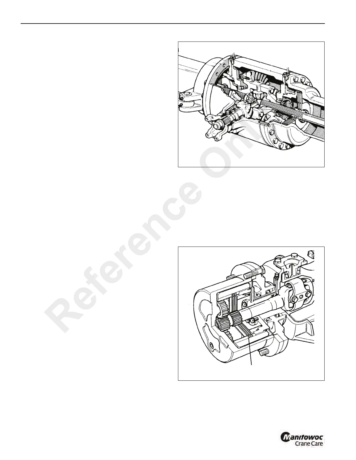
Rear Axle Brakes
The rear brakes are self-adjusting, oil immersed and are
located in each axle hub Figure 9-4. Each brake assembly
consists of three friction plates and four counter plates. The
brakes are applied when the brake pedal in the operator’s
compartment is actuated. Brake fluid is forced from the
master cylinder through the brake lines to both of axle
brakes. The brake fluid under pressure reacts against the
brake pistons, forcing the friction plates against the counter
plates, slowing and/or stopping the crane.
FIGURE 9-4
a0217
Brake Pack
Reference Only

 Loading...


