GROVE Published 10-21-2010, Control# 198-04 10-19
5540F/YB5515 SERVICE MANUAL STEERING SYSTEM
4. Rotate the steering wheel a small amount in each
direction several times, then release to get a balance of
pressure in the steering circuit. Slowly loosen the
hydraulics lines at ports L and R to release any
remaining pressure. Disconnect the hydraulic lines from
IN and OUT ports. Put plugs and caps in the ports and
hydraulic lines.
5. Remove the four bolts which fasten the steering column
and orbitrol to the mounting bracket. Be sure to hold the
steering orbitrol in position while the last bolt is being
removed. Remove the steering orbitrol.
Disassembly
Cleanliness is extremely important when repairing a steering
orbitrol. Work in a clean area. Use a wire brush to remove
foreign materials and debris from around exterior joints of the
unit.
NOTE: Although not all illustrations show the unit in a vice,
we recommend that you keep the unit in a vice
during disassembly. Follow the clamping
procedures explained throughout the instructions.
1. Clamp the unit in a vise, meter end up. Clamp lightly on
the edges of the mounting area Figure 10-18. Use
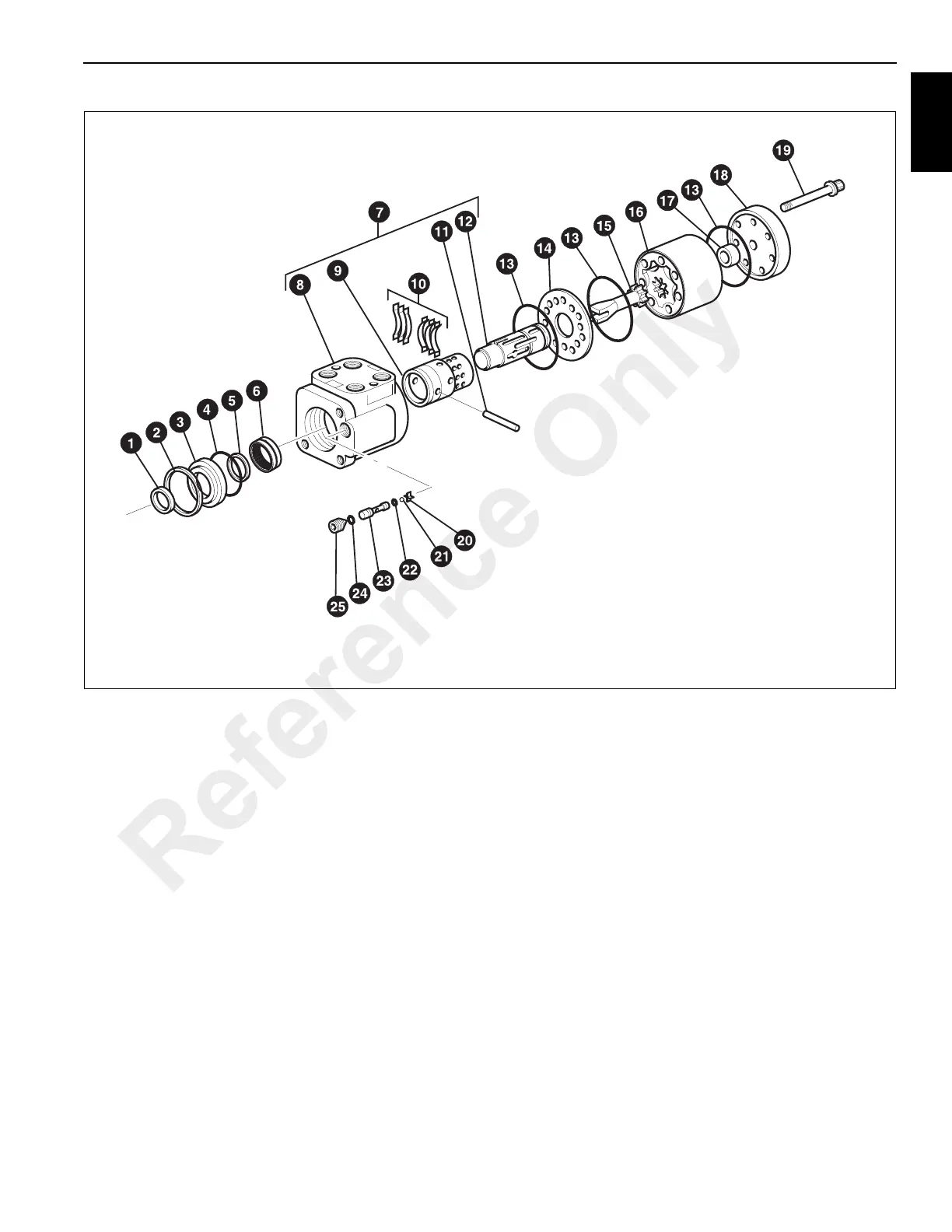
FIGURE 10-17
a0327
Steering Orbitrol
1. Seal
2. Retaining Ring
3. Seal Gland Bushing
4. Seal
5. Quad Ring Seal
6. Needle Bearing Kit
7. Control Part Assembly
8. Housing
9. Control Sleeve
10. Centering Spring (6)
11. Centering Pin
12. Control Spool
13. Seal (3)
14. Spacer Plate
15. Drive
16. Gerotor
17. Spacer
18. End Cap
19. Capscrew (7)
20. Check Ball Retainer
21. Check Ball
22. Seal
23. Seat
24. Seal
25. Set Screw
Reference Only

 Loading...


