STEERING SYSTEM 5540F/YB5515 SERVICE MANUAL
10-20 Published 10-21-2010, Control# 198-04
protective material on the vise jaws. Housing distortion
could result if the vise jaws are overtightened.
2. Remove the seven 6 pt. Torx Drive bolts 19
Figure 10-17. Remove end cap (18). Remove seal (13)
from the end cap.
3. Remove the gerotor (16). Remove seal (13) from gerotor
(16). Remove drive spacer(s) (17).
4. Remove drive (15). Remove spacer plate (14). Remove
seal (13) from housing (8).
5. Remove housing (8) from the vise. Place it on a clean
soft cloth to protect the surface finish. Use a thin bladed
screwdriver Figure 10-19 to pry retaining ring (2,
Figure 10-17 from housing (8).
6. Rotate spool (12) and sleeve (9) until pin (11) is
horizontal. Push the spool and sleeve assembly forward
with your thumbs just far enough to free gland bushing
(3) from the housing. Remove gland bushing (3).
7. Remove quad seal (5) from gland bushing (3).
8. Use a thin bladed screwdriver to pry dust seal (1) from
gland bushing (3). Do not damage the gland bushing.
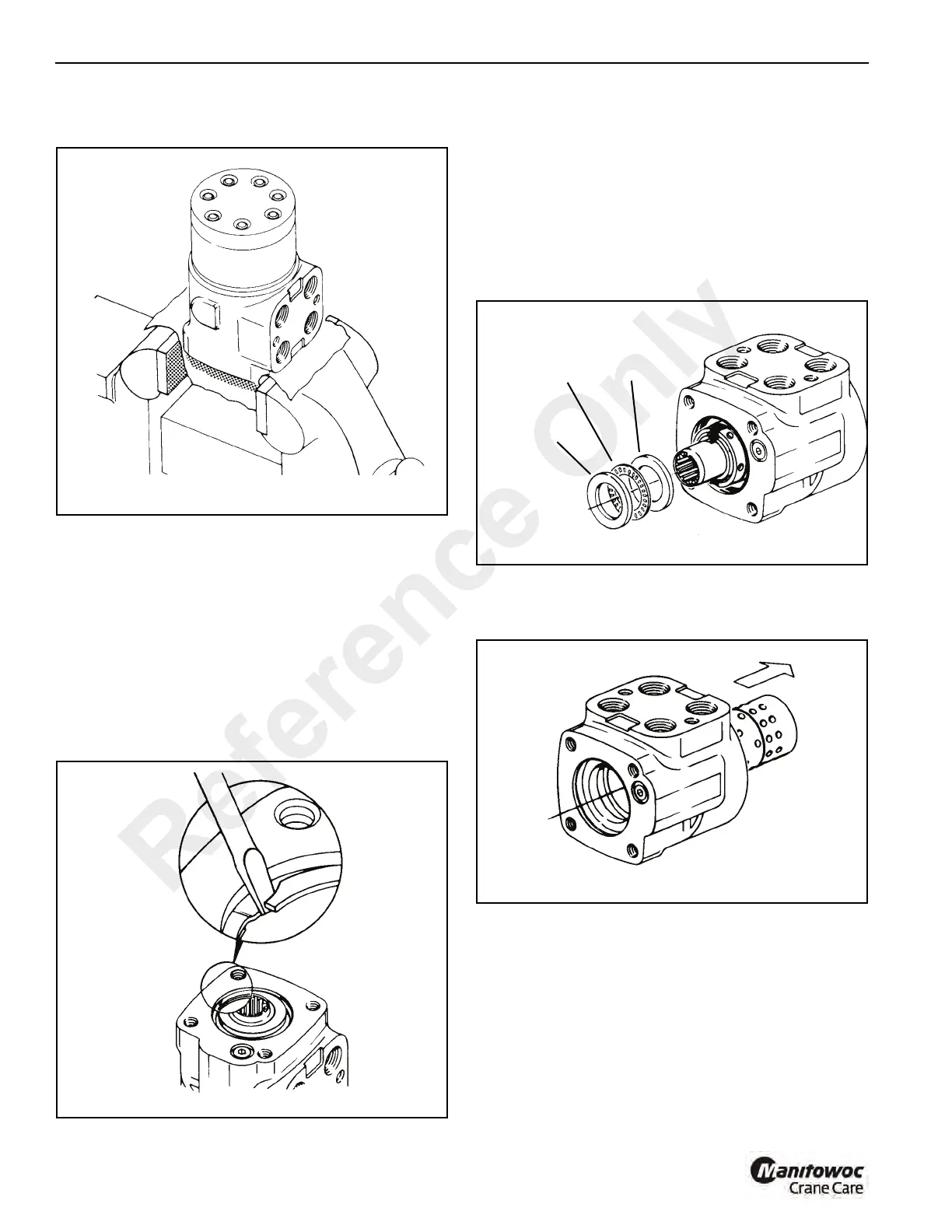
9. Remove needle bearing kit (6). The kit consists of two
bearing races and a needle thrust bearing Figure 10-20.
10. Remove spool and sleeve assembly, 10 through 12,
Figure 10-17. Remove from rear end of housing
Figure 10-21.
NOTE: Do not bind spool and sleeve in the housing.
Rotate the spool and sleeve assembly slowly when
removing from housing.
11. Push pin 11 Figure 10-17 from spool and sleeve
assembly.
12. Push spool (12) partially from control end of sleeve (9).
Remove six centering springs (10) from the spool
carefully by hand Figure 10-22
FIGURE 10-20
a0330
Steering
Column
Bearing
Race
Bearing
Race
Reference Only

 Loading...


