STRUCTURALS 5540F/YB5515 SERVICE MANUAL
11-60
4. Remove four socket head capscrews 21and
lockwashers 25. Remove motor adapter11.
5. Remove gasket 17 and shim 22. Be sure not to damage
or loose the shim.
6. Remove and discard o-ring 34.
7. Remove four capscrews 23 and lockwashers27.
Remove bearing retainer 10 and gasket19.
8. Remove and discard o-ring 34 and seal 31.
9. Using a wench on the hex on the end of the work gear
shaft 6, turn the worm shaft and walk the worm shaft and
bearings 8 and 9 out the end of the worm housing.
10. Remove bearing cones 8 and cups 9 from worm shaft 6.
11. Remove six capscrews 24 and lockwashers 26. Remove
worm gear housing cover 3 and cover gasket 20.
12. Remove retaining ring 12 and then retaining ring 14.
13. Pull worm gear 5 off of output pinion shaft 7. Remove the
remaining retaining ring 12.
14. Pull output pinion 7 from worm housing 1.
15. Remove and discard oil seal 16.
16. If necessary, remove bushing 2 from worm housing 1
and bushing 4 from worm housing cover 3.
Inspection
Clean all parts. See Section 1. Make sure breather (30,
Figure 11-128 is clean. Make a careful inspection of all parts,
including gears, shafts and bearings. Replace all seals and
gaskets.
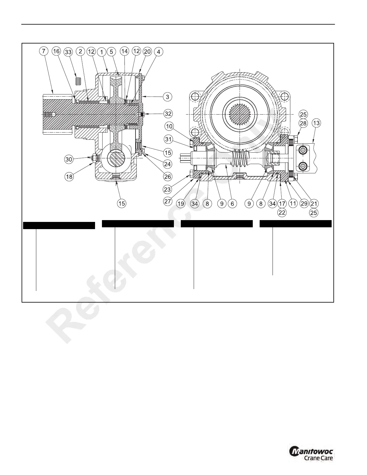
FIGURE 11-128
a2273
Winch Tension Roller Subassembly Cut-Away View
Item Description
1Worm Housing
2 Bushing
3 Worm Housing Cover
4 Bushing
5Worm Gear
6Worm
7 Output Pinion
8 Bearing Cup (2)
9 Bearing Cone (2)
10 Bearing Retainer
11 Motor Adapter
12 Retaining Ring (2)
13 Hydraulic Motor
14 Retaining Ring
15 O-Ring Plug
16 Oil Seal
17 Gasket -0.015” (4)
18 Reducer
Item Description
19 Gasket - 0.031”
20 Cover Gasket
21 Capscrew (4)
22 Shim
23 Capscrew (4)
24 Capscrew (6)
25 Lockwasher (6)
26 Lockwasher (6)
27 Lockwasher (4)
Item Description
28 Capscrew (4)
29 Motor Gasket
30 Relief Valve
31 Seal
32 Pipe Plug
33 Plug
34 O-Ring
Item Description
Reference Only
 Loading...


