GROVE Published 10-21-2010, Control# 198-04 4-15
5540F/YB5515 SERVICE MANUAL HYDRAULIC SYSTEM
4. Actuate the swing control and observe the pressure
gauge attached to the pump outlet. The relief valve
should open at 2000 ± 50 psi (138 ± 3.5 bar). Release
the control lever after the reading is obtained.
5. If the pressure reading is correct, stop the engine and
remove the pressure gauge. Connect the two hoses to
the swing motor.
6. If the pressure reading is incorrect, adjust the pressure
setting for the swing circuit relief valve.
Boom Lift/Telescope/Outrigger Circuit Main Relief
Valve Test
The boom lift circuit, telescope circuit and outrigger circuits
are protected by the same relief valve. To test the relief valve
it is recommended that the boom lift circuit be used for
testing purposes.
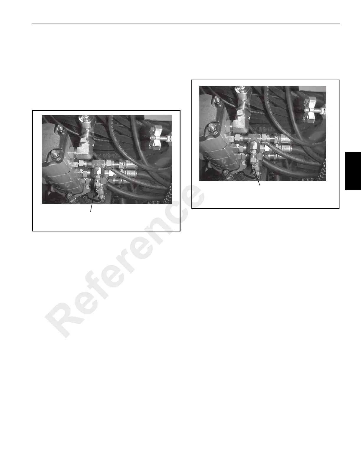
1. With the engine shut off and the parking brake engaged,
connect a 0 -5000 psi (0 - 345 bar) to the test connection
on the pressure side of the telescope/outrigger section
of the hydraulic pump (Figure 4-15).
2. Start the engine and accelerate it to full rpm.
3. Actuate the boom lift control to fully lower the boom.
Hold the control in position and observe the pressure
gauge attached to the pump outlet. The relief valve
should open at 3500 ± 50 psi (241 ± 3.5 bar). Release
the control lever after the reading is obtained.
4. If the pressure reading is correct, stop the engine and
remove the pressure gauge.
5. If the pressure reading is incorrect, adjust the pressure
setting for the boom lift, telescope/outrigger circuit relief
valve.
Winch Hoist Circuit Main Relief Valve Test
1. With the engine shut off and the parking brake engaged,
connect a 0 - 5000 psi (0 - 345 bar) to the test
connection on the pressure side of the winch hoist/boom
lift section of the hydraulic pump (Figure 4-16).
2. Disconnect the hoist brake line between the brake valve
and the hoist brake housing. Cap and plug the openings.
3. Start the engine and accelerate it to full rpm.
4. Actuate the boom lift control to fully lower the booms.
Hold the control in position and observe the pressure
gauge attached to the pump outlet. The relief valve
should open at 3500 ± 50 psi (241 ± 3.5 bar). Release
the control lever after the reading is obtained.
5. If the pressure reading is correct, stop the engine and
remove the pressure gauge.
6. If the pressure reading is incorrect, adjust the pressure
setting for the winch hoist circuit relief valve.
7. Reconnect the brake line.
p1636
Swing Circuit Test Relief Valve Test Connection
FIGURE 4-14
Boom Lift/Telescope/Outrigger Circuit Relief Valve Test
Connection
FIGURE 4-15
p1636
Reference Only

 Loading...


