4-45
Published 10/19/2017, Control # 618-00
GRT880 SERVICE MANUAL BOOM
76. Fully tighten right side middle wear pad adjusting bolt
(244). Install shim (219) on top of right side wear pads by
gently tapping with a rubber mallet or block of wood (see
Figure 4-116).
77. Fully loosen right side middle wear pad adjusting bolt
(244) and then fully tighten left side middle wear pad
adjusting bolt (244). Install shim (219) on top of left side
wear pads by gently tapping with a rubber mallet or block
of wood. Fully loosen left side middle wear pad adjusting
bolt (244).
78. Install, but do not tighten, twelve set screws (239)
through tele 2 (301) and into the three bars (211, qty 2 -
210) holding the wear pads. Install a washer (235) and
jam nut (251) onto each set screw (239).
79. Slightly tighten the left and right side bottom and middle
wear pad adjusting bolts (249). Slightly tighten the
twelve set screw (239). Final tightening of these bolts
and sets screws is done after assembly is completed
and boom is installed on to the crane.
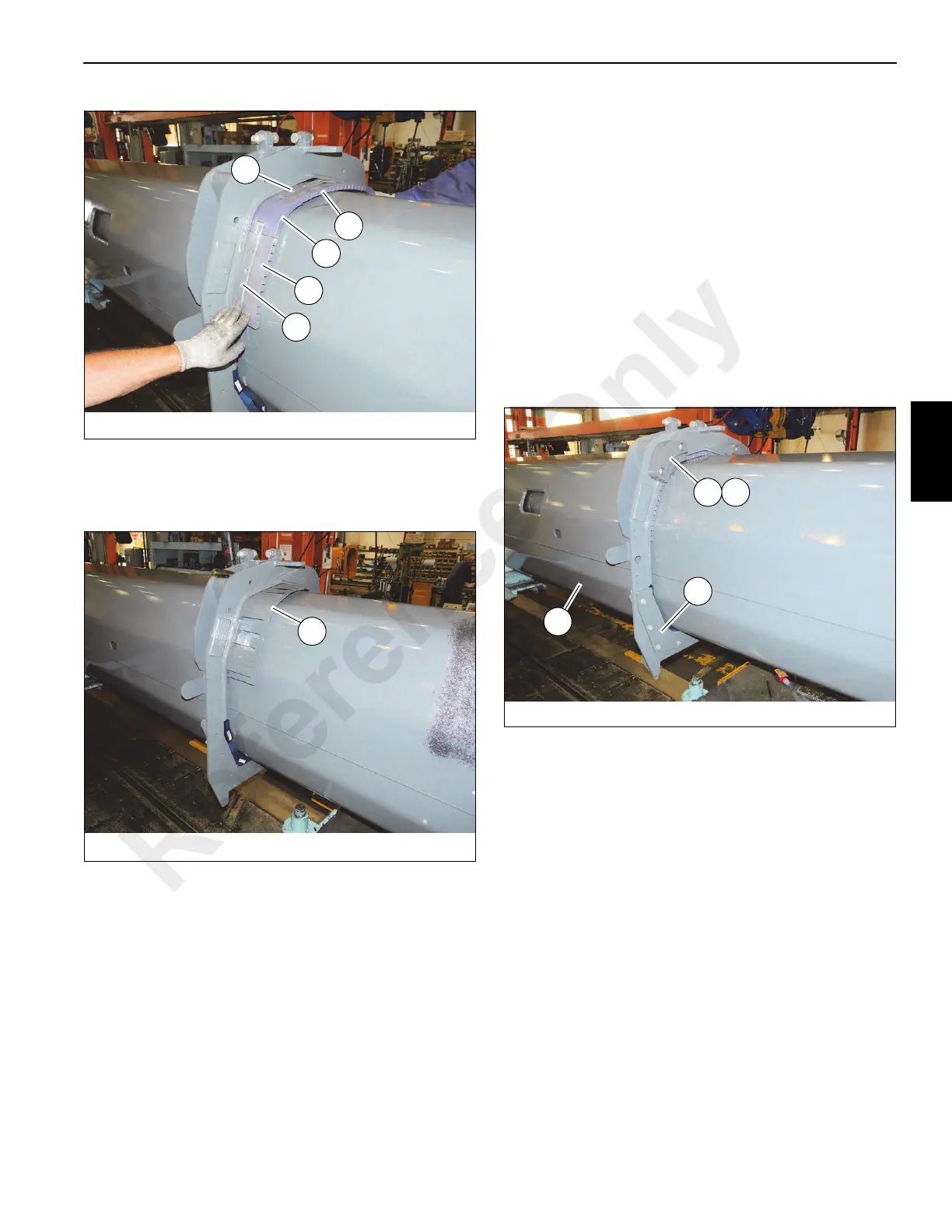
80. Install top left and right (as oriented) side shims (217)
and stop blocks (218) on front of tele 1 (201) using bolts
(245). Ensure tab of shim is towards the very top of tele
1 (201) (see Figure 4-117).
81. Install bottom left and right (as oriented) side stop plates
(216) on to front of tele 1 (201) using bolts, washers, lock
washers, and nuts (238, 235, 236, 247) (see
Figure 4-117).
82. Fully insert tele 2 (301) into tele 1 (201), ensuring
cylinders #1 (502) and #2 (501) pass through rear of tele
1 (201) without hitting.
83. Apply anti-seize to pins (213), then install a pin through
each side of tele 1 (201) and into holes in plates (503)
which connect cylinders #1 (502) and #2 (501) together.
FIGURE 4- 115
9044-60
207
206
210
209
211
FIGURE 4- 117
9044-61
218217
201
216
Reference Only

 Loading...


