BOOM GRT880 SERVICE MANUAL
4-46
Published 10/19/2017, Control # 618-00
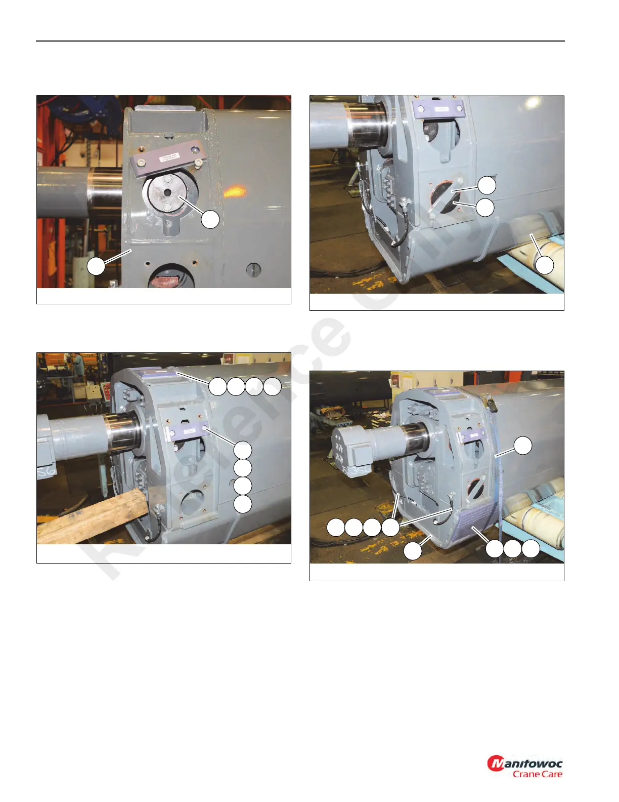
Secure each pin (213) with two bolts and washers (231,
243) (see Figure 4-118).
84. Install side wear pad (224) and shims (222, 223) to
bottom set of mounting holes (P) using bolts (225) (see
Figure 4-119) (left and right sides).
85. Install top wear pads (Q, 224) and shims (223, 222)
using bolts (225) (see Figure 4-119).
86. Apply anti-seize to pins (214), then install a pin through
each side of tele 1 (201) and into holes in plates (503)
508) which connect telescope cylinder #1 (502) and #2
(501) together. Secure each pin (214) with a plate (215)
and two bolts (242) (see Figure 4-120).
87. Install grease hose (208) and fittings (227, 228, 229) to
rear of tele 1 (201). Ensure grease fittings point outward
and hoses pass through holes in the gussets of tele 1
(201) (see Figure 4-120).
88. Install shims (212) and wear pads (202, 203) to bottom
(as oriented) of tele 1 (201). Align holes in shims with
pins on tele 1. Attach grease hose assemblies to rear
hole of each wear pad (202). Secure wear pads to tele 1
(201) using a ratchet strap (R) (see Figure 4-121).
89. Position base (101) upside down on adequate supports
behind tele 1 (201).
90. Apply multipurpose grease to inside top, sides, and
bottom of base (101) in the areas where the wear pads
of tele 1 (201) will touch.
FIGURE 4- 118
9044-62
213
201
FIGURE 4- 119
9044-63
223
224
222
P
223 224222Q
FIGURE 4- 120
9044-64
214
215
201
FIGURE 4- 121
9044-65
228208 227 229
201
212203202
R
Reference Only

 Loading...


