Published 4-22-15, Control # 556-00 4-15
RT530E-2 SERVICE MANUAL BOOM
5. Lay out the extend synchronizing cable on top of the
outer mid with both threaded ends at the rear and the
loop at the front. Route the looped end through the
inside of the sheaves installed in step 4. Place the
looped end around the fixed half sheave at rear of the
outer mid. Be careful to not twist cable.
6. Install a socket head keeper bolt on each side of the half
sheave to retain the cable.
7. Position the front end of the outer mid at the rear of the
fly/telescope cylinder assembly.
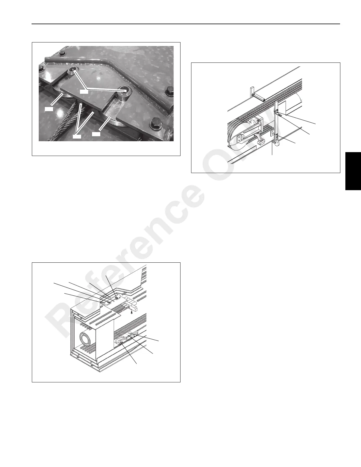
8. Using pins, cotter pins, and safety clip (1) attach the four
fly retract cables (2) laying in the bottom of the outer mid
to the lugs in the rear of the fly (3) (Figure 4-26).
9. Slide the fly/telescope cylinder into the outer mid being
careful not to damage any of the cables. As the sections
slide together pull the retract cables out the rear of the
outer mid. Do not fully slide together.
10. Lift up on the front of the fly and install the bottom front
wear pads (1) (Figure 4-27) in the pockets of the outer
mid.
11. Install outer mid front top (4) and bottom (2) side wear
pads with two screws each. On top left side attach
mounting angle (3) with top wear pad screw
(Figure 4-27). Shim as noted during disassembly.
12. Install kicker plate in top of outer mid with capscrews.
13. Completely slide assembly together.
14. Turn cylinder rod mounting lugs so they are horizontal
with port block holding valve being at the top.
15. Loosen plugs in cylinder port block and manually extend
the inner rod approximately 15 to 20 cm (6 to 8 in).
Tighten plugs.
16. Lift up on end of cylinder to align barrel mounting holes
with tabs and holes in lugs of outer mid. Secure with two
bolts and washers.
17. Remove any blocking under cylinder.
18. Through the top access hole in the outer mid, position
the two adjustable wear pads (4) on the top rear of the
fly. Install each wear pad holder (5) and loosely install
each with two capscrews and washers (6) (Figure 4-26).
Install offset washers, capscrews and washers (7).
Using the offset washers, adjust the wear pads such that
the wear pads are within 1 mm (0.03 in) from each side
plate of the next outer section. Tighten the offset washer
and capscrews.
19. Route the four fly retract cables through the holes in the
bottom of the outer mid and pull them toward the front of
the assembly. Install the anchor plates on the cables
with cable locknuts. Be careful not to tangle cables.
20. Apply grease to four thrust washers and place one on
each side of the two groove retract cable sheave
assemblies. Grease will keep the thrust washer in place
during installation.
FIGURE 4-26
6960-14
2
1
3
4
5
6
7
6
Reference Only

 Loading...


