4-19
Published 11/26/2014, Control # 447-05
RT770E SERVICE MANUAL BOOM
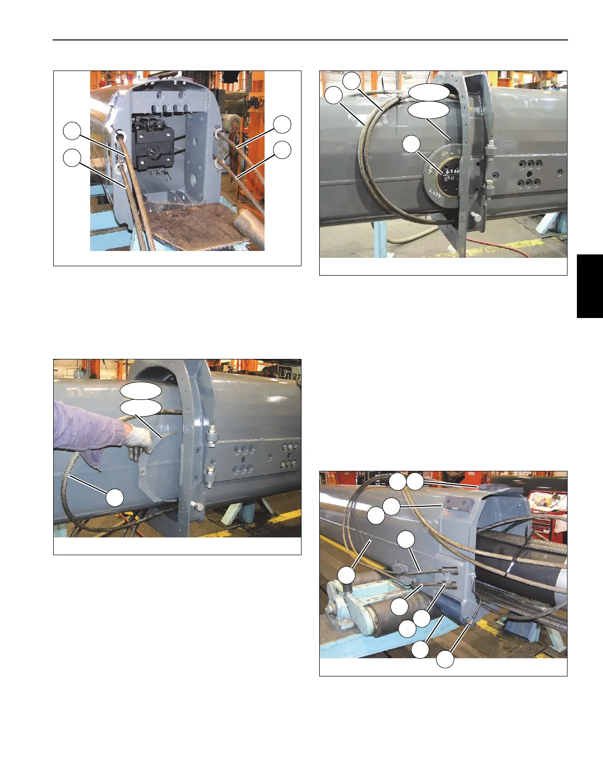
73. Extend tele 4 (5) one-quarter of the way out of tele 3 (4).
74. Remove the grease fitting (106) from each of the four
shafts (104).
75. Remove the capscrew (113) securing the front guard
weldment (112) over the tele 4 extend cable (110) (left
and right sides) (see Figure 4-22).
76. Pull the tele 4 forward extend cables (110) away from
the front sheaves (108).
77. Remove the six capscrews (105) and shaft (104)
securing the front sheave (108) to the inside of tele 3 (4)
(left and right sides) (see Figure 4-23).
.
78. Remove capscrew (113) securing the rear guard
weldment (111) over the tele 4 extend cable (109) (left
and right sides) (see Figure 4-22).
79. Pull the tele 4 forward extend cables (109) away from
the rear sheaves (107) (see Figure 4-23).
80. Remove the six capscrews (105) and shaft (104)
securing the rear sheave (107) to the inside of tele 3 (4)
(left and right sides) (see Figure 4-23).
81. Remove tele 4 (5) from tele 3 (4); set tele 4 (5) on
adequate supports.
82. Remove the capscrew (130) and cable anchor (129)
securing the tele 4 extend cables (109, 110) to the side
of the rear of tele 4 (5) (left and right sides) (see
Figure 4-24).
FIGURE 4-21
8008-10
109
110
110
109
FIGURE 4-22
8008-8
111
112
Front
Rear
110
FIGURE 4-23
8008-7
104
108
Front
110
109
107
Rear
FIGURE 4-24
8008-6
135
127
129
109
110
128
134
130
5
70
70
 Loading...


