BOOM RT770E SERVICE MANUAL
4-18
Published 11/26/2014, Control # 447-05
63. Remove the four bolts (119) and flat washers (118)
securing the sheave mount weldment (117) to the inside
of tele 3 (4), then remove the sheave mount weldment/
sheave assembly (116/117) along with the three thrust
washers (115) (left and right sides) (see Figure 4-19).
.
64. Extend tele 4 (5) one-quarter of the way out of tele 3 (4).
65. Remove the two bolts (58), four washers (16), two lock
washers (17), and two nuts (18) securing the stop block
(56) to the front of tele 3 (4) (left and right sides) (see
Figure 4-20).
66. Remove the bolts (19), flat washers (16), lock washers
(17), and nuts (18) securing the left, right, and bottom
keeper plates (2x-14, 13) to the front of tele 3 (4) (see
Figure 4-20).
67. Remove the front lower wear pads (101, 102) and shims
(100) from the bottom of tele 3 (4).
68. Using an adequate lift and sling, slightly raise the front of
tele 4 (5) for the purpose of removing the wear pads
from the front of tele 3 (4).
69. Remove the three bolts (19), six flat washers (16), three
lock washers (17), and three nuts (18) securing the
keeper plate (15) to the front of tele 3 (4) (left and right
sides) (see Figure 4-20).
70. Remove the two bolts (27) and nuts (28) securing the
upper wear pad (103) to the front of tele 3 (4) (left and
right sides) (see Figure 4-20).
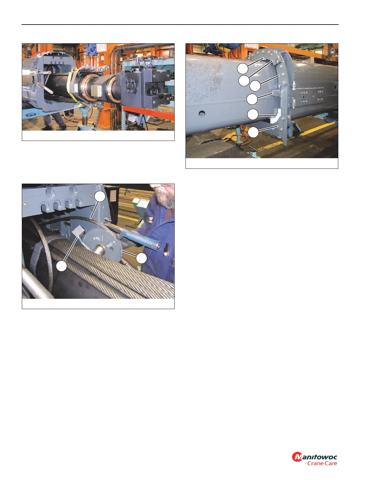
71. Remove the two bolts (105) securing the anti-roll plate
(114) to the inside of tele 3 (4) (left and right sides) (see
Figure 4-20).
72. Remove the tele 4 extend cables (109, 110) from the
slotted holes in the rear of tele 3 (4) (see Figure 4-21).
FIGURE 4-19
8008-13
117
116
131
FIGURE 4-20
8008-11
103
15
114
14
13
56
 Loading...


