4-17
Published 11/26/2014, Control # 447-05
RT770E SERVICE MANUAL BOOM
49. Remove the bolts (19), flat washers (16), lock washers
(17), and nuts (18) securing the left, right, and bottom
keeper plates (2x-14, 13) to the front of tele 2 (3) (see
Figure 4-15).
50. Remove front lower wear pads (90, 91) and shims (89)
from the bottom of tele 2 (3).
51. Using an adequate lift and sling, slightly raise the front of
tele 3 (4) for the purpose of removing wear pads from
the front of tele 2 (3).
52. Remove the three bolts (19), six flat washers (16), three
lock washers (17), and three nuts (18) securing the
keeper plate (15) to the front of tele 2 (3) (left and right
sides) (see Figure 4-15).
53. Remove the two bolts (27) and nuts (28) securing the
upper wear pad (92) to the front of tele 2 (3) (left and
right sides) (see Figure 4-15).
54. Remove tele 3 (4) from tele 2 (3); set tele 3 (4) on
adequate supports.
55. Remove the wear pad (94)/grease hose assembly (126,
79, 80, 77, 78) from the attaching bracket on each side
of the rear of tele 3 (4).
56. Remove the two capscrews (83) and lock washers (72)
securing the wear pad assembly (71) to each side of the
bottom rear of tele 3 (4).
57. Remove the two capscrews (83) securing the wear pad
assembly (82) to each side of the bottom rear of tele 3
(4).
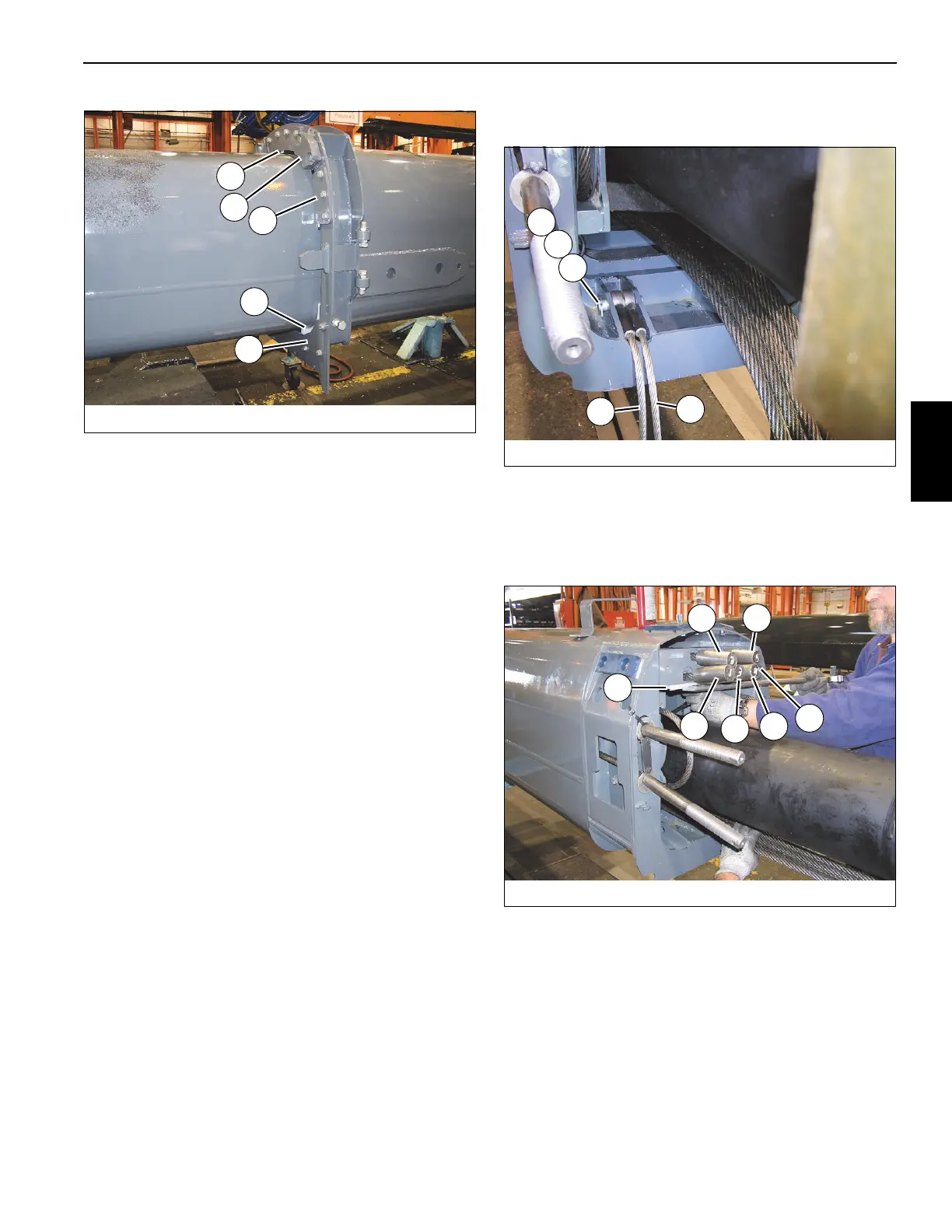
58. Remove the two cotter pins (122), two flat washers
(121), and pin (120) securing the two tele 3 retract
cables (65) to the rear of tele 3 (4) (left and right sides)
(see Figure 4-16).
59. Remove the two bolts (124) and lock washers (25)
securing the cable keeper (125) to the rear of tele 3 (4).
60. Remove the two bolts (124) and lock washers (25)
securing the cylinder wear pad (123) to the top of the
anchor point at the rear of tele 3 (4) (see Figure 4-17).
61. Remove the six tele 3 extend cables (150), labeled 1
through 6, from the anchor points at the rear of tele 3 (4)
(see Figure 4-17).
62. Duct tape the six tele 3 extend cables (150) to the top of
the cylinder (see Figure 4-18).
FIGURE 4-15
8008-18
15
14
13
56
92
FIGURE 4-16
8008-15
122
121
120
65
65
FIGURE 4-17
8008-14
#2
#1
#5
#3
#4
#6
123
 Loading...


